Connector

Active Publication Date: 2016-10-06
SUMITOMO WIRING SYST LTD
View PDF1 Cites 4 Cited by
  • Summary
  • Abstract
  • Description
  • Claims
  • Application Information

AI Technical Summary

Benefits of technology

[0012]The terminal fitting and the sleeve can be integrally temporarily assembled. For example, if, in sealing the end of the wire by a heat shrinkable tube, the heat shrinkable tube fitted on the wire connecting portion of the terminal fitting is heated in a state accommodated in the sleeve, the terminal fitting

Problems solved by technology

If the terminal fitting is inclined before being connected to a mating terminal, there may be difficulty in connecting the terminals due to a mutual displacement of axial centers.
Further, if the terminal fit

Method used


Image

  • Connector
  • Connector
  • Connector

Examples


Example

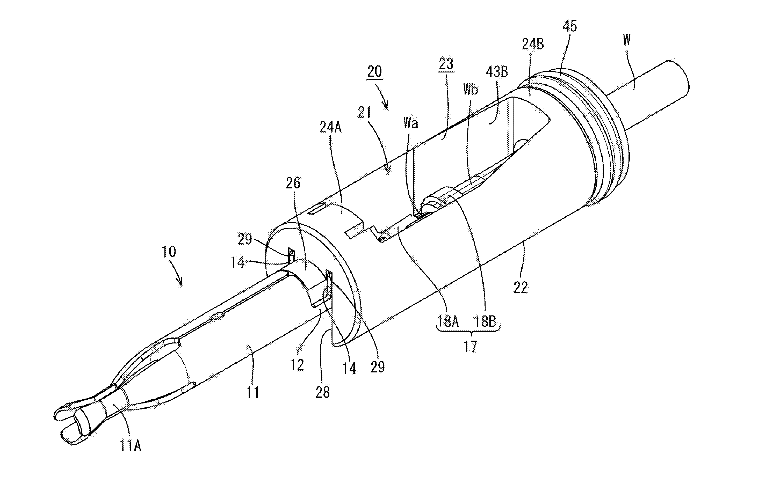
[0032]A charging connector C is illustrated and mounted on the tip of a gun-shaped case (not shown) and connected to a vehicle-side connector provided in a vehicle. The charging connector C of this embodiment (hereinafter, merely referred to as the connector C) is a five-pole connector and includes terminal fittings 10 connected to ends of wires W and a housing 50 for accommodating the terminal fittings 10 as shown in FIG. 18. The terminal fittings 10 are composed of two power terminals, one ground terminal and two signal terminals and basic structures thereof are similar although diameters and the like may be different depending on the type. The following description is given, taking the signal terminal as an example.

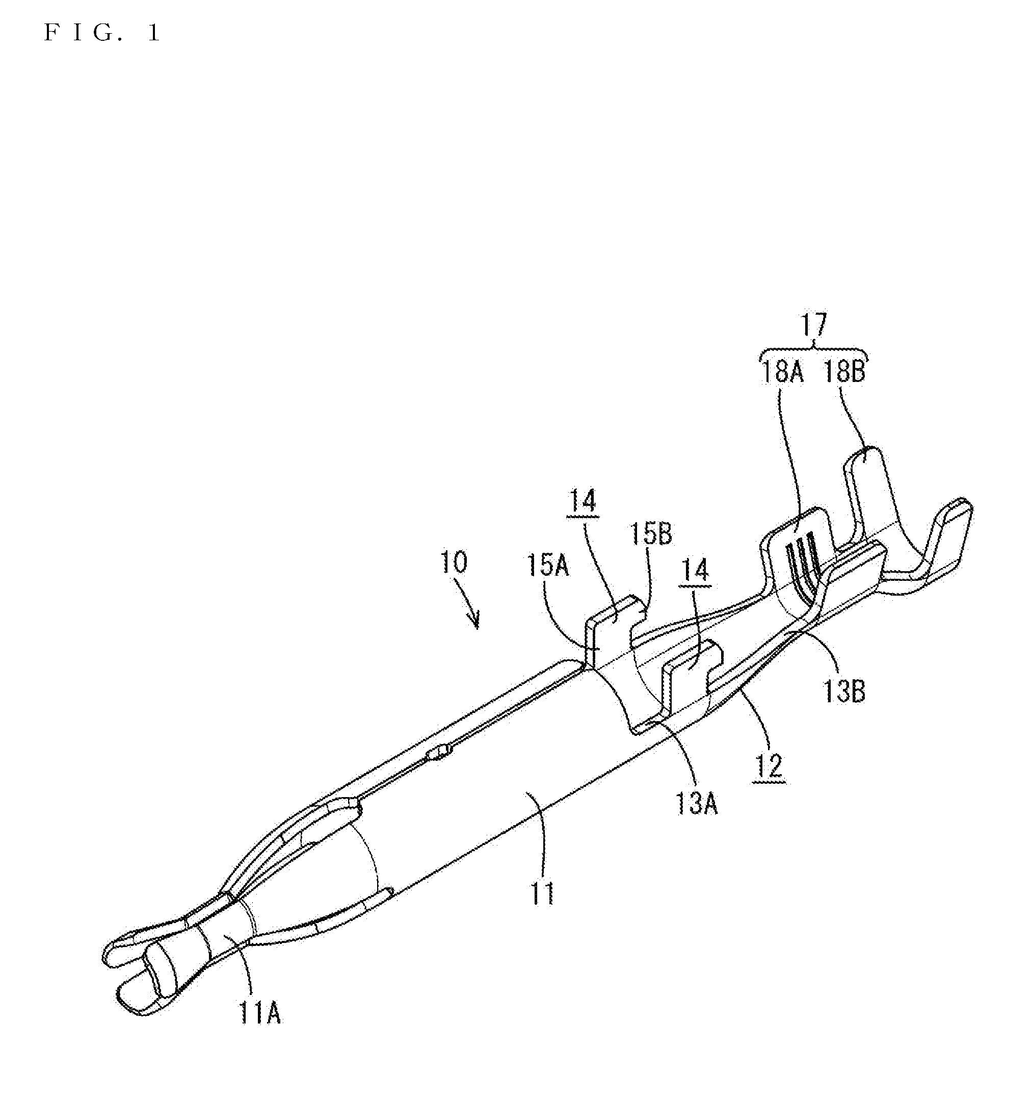
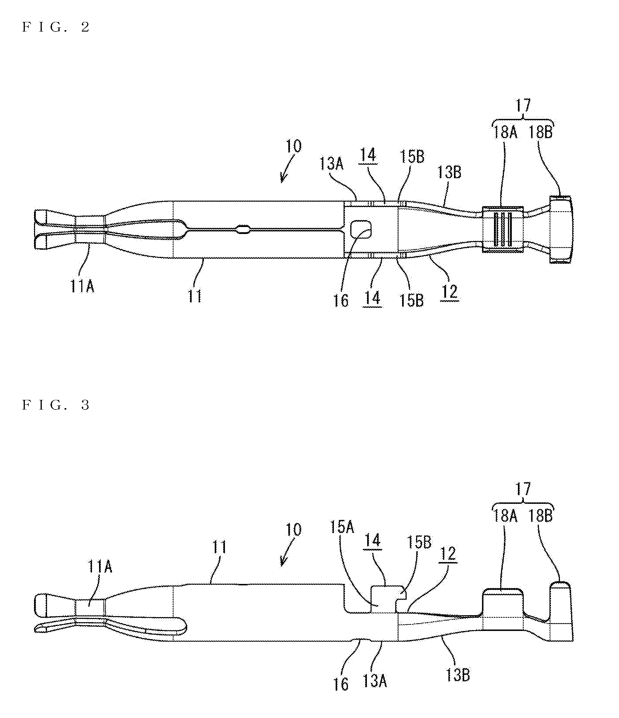
[0033]The terminal fitting 10 is a female terminal and formed into a shape as shown in FIGS. 1 to 3 by press-forming a metal plate with excellent electrical conductivity. The terminal fitting 10 is so formed that a terminal connecting portion 11 to be connected to a ma...


PUM


Abstract

It is aimed to maximally suppress the inclination of a terminal fitting in a terminal accommodating chamber. A connector includes a terminal fitting having a wire connecting portion connected to an end of a wire, a housing having a terminal accommodating chamber into which the terminal fitting is to be inserted from behind, and a sleeve fitted on a rear side of the terminal fitting while surrounding the wire connecting portion of the terminal fitting and functioning to retain the terminal fitting by locking both front and rear end parts to the terminal fitting and a wall surface of the terminal accommodating chamber. An inclination regulating portion configured to regulate such inclination of the terminal fitting relative to the sleeve as to incline axial lines of the terminal fitting and the sleeve relative to each other is provided near a fitting part of the terminal fitting and the sleeve.

Description

BACKGROUND[0001]1. Field of the Invention[0002]The present invention relates to a connector.[0003]2. Description of the Related Art[0004]Japanese Unexamined Patent Publication No. 2014-75298 discloses a charging connector with a means for retaining and accommodating a terminal fitting at a predetermined position in a housing. The charging connector includes a spacer formed of a sleeve made of resin and mounted to cover a wire connecting portion. The terminal fitting includes the wire connecting portion crimped to an end of a wire and is structured such that the terminal fitting is inserted into a terminal accommodating chamber of the housing together with the spacer. The terminal fitting is locked to the front end of the spacer and the rear end of the spacer is locked to a rear end part of the terminal accommodating chamber to retain the terminal fitting at a predetermined position in the terminal accommodating chamber of the housing.[0005]In the above described charging connector, ...

Claims


Application Information

Patent Timeline
IPC IPC(8): H01R13/426
CPCH01R13/426H01R4/185H01R13/111H01R13/42
Inventor UCHIDA, MASASHI
Owner SUMITOMO WIRING SYST LTD
Why Eureka
Try Eureka