Ignition plug

a plug and plug-in technology, applied in the direction of spark plugs, spark plugs, basic electric elements, etc., can solve the problems of sway of sparks, misfiring risk, spark size, etc., to prevent or reduce erosion and uneven wear of ground electrodes, prevent or reduce separation between ground electrodes and noble metal chips, and prevent or reduce erosion of ground electrodes.

Active Publication Date: 2016-10-06
NGK SPARK PLUG CO LTD
View PDF4 Cites 0 Cited by
  • Summary
  • Abstract
  • Description
  • Claims
  • Application Information

AI Technical Summary

Benefits of technology

[0010]According to the ignition plug of the first aspect, erosion and uneven wear of the ground electrode can be prevented or reduced without using a noble metal or a noble metal alloy, and the occurrence of separation between the ground electrode and a noble metal chip can be prevented or reduced.
[0011]In the ignition plug according to the first aspect, the center-electrode-facing portion may have a projection that projects beyond the second layer. In this case, erosion of the ground electrode can be more reliably prevented or reduced.
[0012]In the ignition plug according to the first aspect, the projection may be bonded to the first layer. In this case, it is possible to prevent or suppress a reduction in the bonding strength between the ground electrode and the projection, and the occurrence of separation of the projection from the ground electrode can be prevented or reduced.
[0013]In the ignition plug according to the first aspect, the projection contains a noble metal as a main component. In this case, erosion of the projection can be reduced.
[0014]In the ignition plug according to the first aspect, the second layer may be arranged so as to extend over an entire region of the inner surface of the ground electrode, and the thickness t1 of the second layer may be 0.2 mm or less in a region from a second center-electrode-facing portion that faces a front-end peripheral portion of the center electrode at a fixed-end side to the fixed end. In this case, it is possible to prevent or suppress a reduction in the bonding strength between the ground electrode and the metal shell, and the occurrence of an abnormality in the bonding region between the metal shell and the ground electrode can be prevented or reduced.
[0015]In the ignition plug according to the first aspect, the second layer may be made of a nickel (Ni) alloy or an iron (Fe) alloy that differs from a material of the first layer. In this case, erosion and uneven wear of the ground electrode can be prevented or reduced without using a noble metal or a noble metal alloy, and the occurrence of separation between the ground electrode and a noble metal chip can be prevented or reduced.

Problems solved by technology

The increase in the size of the spark and the time period for which electricity is supplied tend to cause sway of the spark.
As a result, there is a risk of misfiring due to separation of a noble metal chip bonded to the ground electrode or breakage of the ground electrode.
In particular, erosion of a base portion of the ground electrode leads to a breakage of the ground electrode, resulting in a reduction in the performance of the ignition plug.
When the ground electrode is protected simply by being coated with a noble metal or the like, the cost thereof is increased.
The related art does not sufficiently address these problems.
Furthermore, in the ground electrode structure including a noble metal chip, the structure for preventing or reducing uneven wear of the base material of the ground electrode and satisfactory bondability between the ground electrode and the noble metal chip have not been sufficiently studied.

Method used


Image

  • Ignition plug
  • Ignition plug
  • Ignition plug

Examples


experiment 1

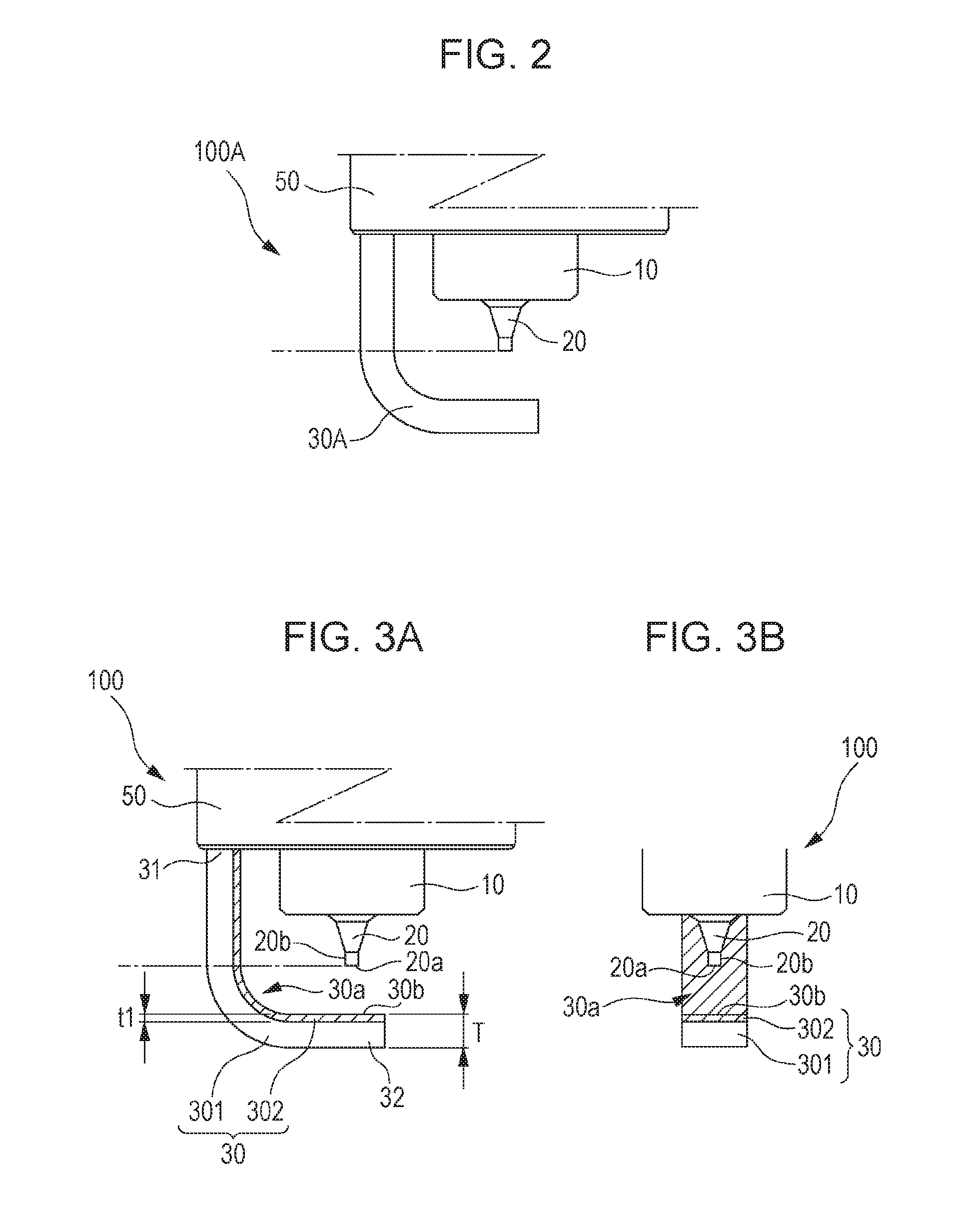
[0046] In Experiment 1, the base material layer 301 was made of material 1 and the erosion-resistant layer 302 was made of materials 2 to 5. As a comparative example, the amount of erosion caused when a ground electrode including only the base material layer 301 was used was determined to be 2.8 mm3. Table 3 shows the result of Experiment 1. In Table 3, “BR” indicates that breakage of the ground electrode 30 occurred.

TABLE 3BaseMaterialErosion-Material 1 Thickness 1.3 mmResistantMaterial 2Material 3Material 4Material 5MaterialAmount of Erosion (mm3)Thickness0.12.72.52.32.2t1 of0.22.71.81.61.5Erosion-0.42.71.71.51.4Resistant0.62.71.71.51.4Layer (mm)0.82.7BRBRBR1.02.7BRBRBR

[0047]When the erosion-resistant layer 302 was made of material 2, the amount of erosion of the entire body of the ground electrode 30 was 2.7 mm3 irrespective of the thickness t1. When the erosion-resistant layer 302 was made of material 3, the amount of erosion of the entire body of the ground electrode 30 was 1.8...

experiment 2

[0048] In Experiment 2, the base material layer 301 was made of material 2 and the erosion-resistant layer 302 was made of materials 3 to 5. As a comparative example, the amount of erosion caused when a ground electrode including only the base material layer 301 was used was determined to be 2.7 mm3. Table 4 shows the result of Experiment 2. In Table 4, “BR” indicates that breakage of the ground electrode 30 occurred.

TABLE 4Base MaterialMaterial 2 Thickness 1.3 mmErosion-ResistantMaterial 3Material 4Material 5MaterialAmount of Erosion (mm3)Thickness t1 of0.12.42.32.2Erosion-Resistant0.21.81.51.5Layer (mm)0.41.71.51.40.61.61.51.40.8BRBRBR1.0BRBRBR

[0049]When the erosion-resistant layer 302 was made of material 3, the amount of erosion of the entire body of the ground electrode 30 was 1.8 mm3 or less for the thickness t1 of 0.2 mm or more and 0.6 mm or less. When the thickness of the erosion-resistant layer 302 was 0.8 mm or more, that is, when the thickness of the base material layer ...

experiment 3

[0052]performed by using material 3 as the material of the base material layer 301. As a comparative example, a ground electrode 30 including only the base material layer 301 was tested. As a result, physical breakage of the ground electrode 30 occurred due to vibration. This is probably because the tensile strength of material 3 was 480 (Mpa), as shown in Table 2, and durability against a vibration of 30 G and a temperature of 800° C. was not sufficient. Therefore, experiments with the base material layer 301 made of materials 3 to 5 and the erosion-resistant layer 302 made of materials 4 and 5 could not be performed.

[0053]In the first study, the ground electrode 30 in which the erosion-resistant layer 302 was formed over the entire region of the inner surface 30a was used. Alternatively, a ground electrode 30 illustrated in FIG. 4 may instead be used. This ground electrode 30 has a two-layer structure including, in addition to the base material layer 301, the erosion-resistant lay...


PUM


Abstract

An ignition plug having a ground electrode that includes a base material layer and an erosion-resistant layer having a thermal conductivity of 40 w / m·K or more. The erosion-resistant layer extends at least from the center-electrode-facing portion to a location closer to the fixed end than a front end of the center electrode and 0.2 mm≦thickness t1 of the erosion-resistant layer≦thickness T of the ground electrode 30−0.6 mm is satisfied.

Description

RELATED APPLICATIONS[0001]This application claims the benefit of Japanese Patent Application No. 2015-075602, filed Apr. 2, 2015, the entire contents of which are incorporated herein by reference.FIELD OF THE INVENTION[0002]The present invention relates to an ignition plug used to ignite an air-fuel mixture in an internal combustion engine.BACKGROUND OF THE INVENTION[0003]An electrode material with which thermal resistance, corrosion resistance, and thermal conductivity can be increased without using a noble metal or a noble metal alloy has been proposed as an electrode material for a center electrode and a ground electrode of an ignition plug (see, for example, Japanese Unexamined Patent Application Publication No. 5-114457).[0004]In recent years, to increase the fuel efficiency of a vehicle and meet emissions regulations that have become more and more severe every year, an air-fuel ratio in the lean range, in which the air-fuel ratio is lower than the stoichiometric air-fuel ratio...

Claims


Application Information

Patent Timeline
Patent Type & Authority Applications(United States)
IPC IPC(8): H01T13/32H01T13/39
CPCH01T13/39H01T13/32H01T13/16
Inventor YAMADA, YUICHIKAWADE, TAKUYA
Owner NGK SPARK PLUG CO LTD
Why Eureka
Try Eureka