

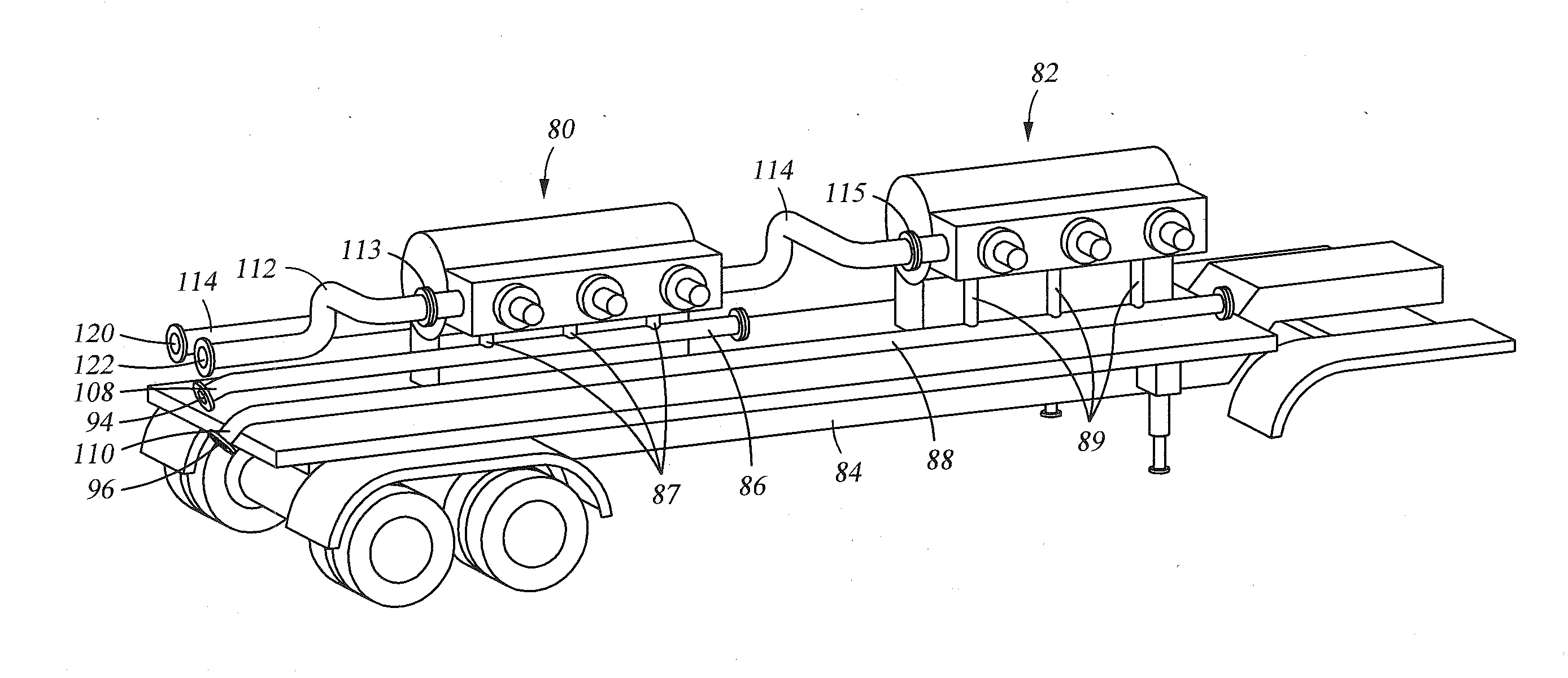
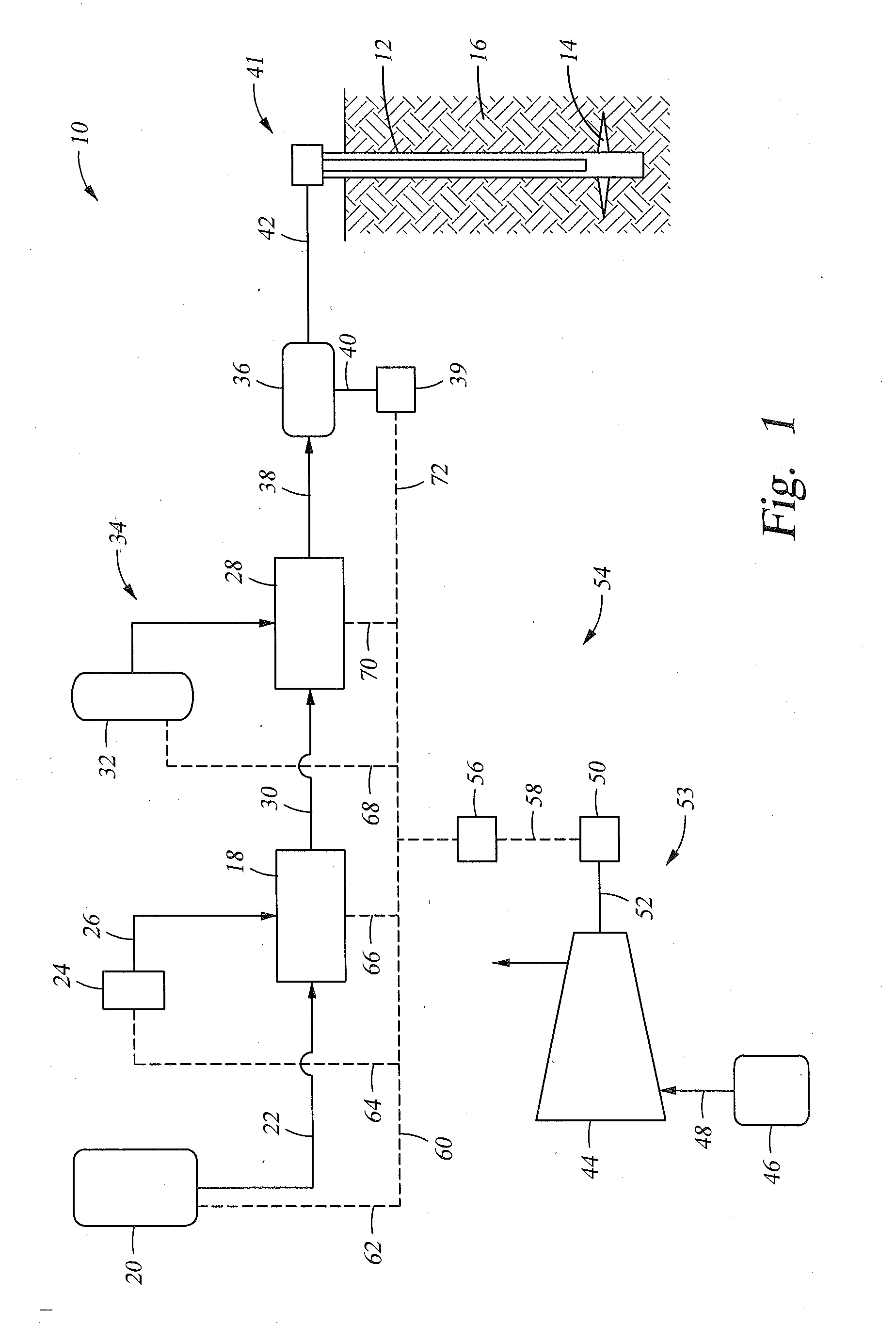
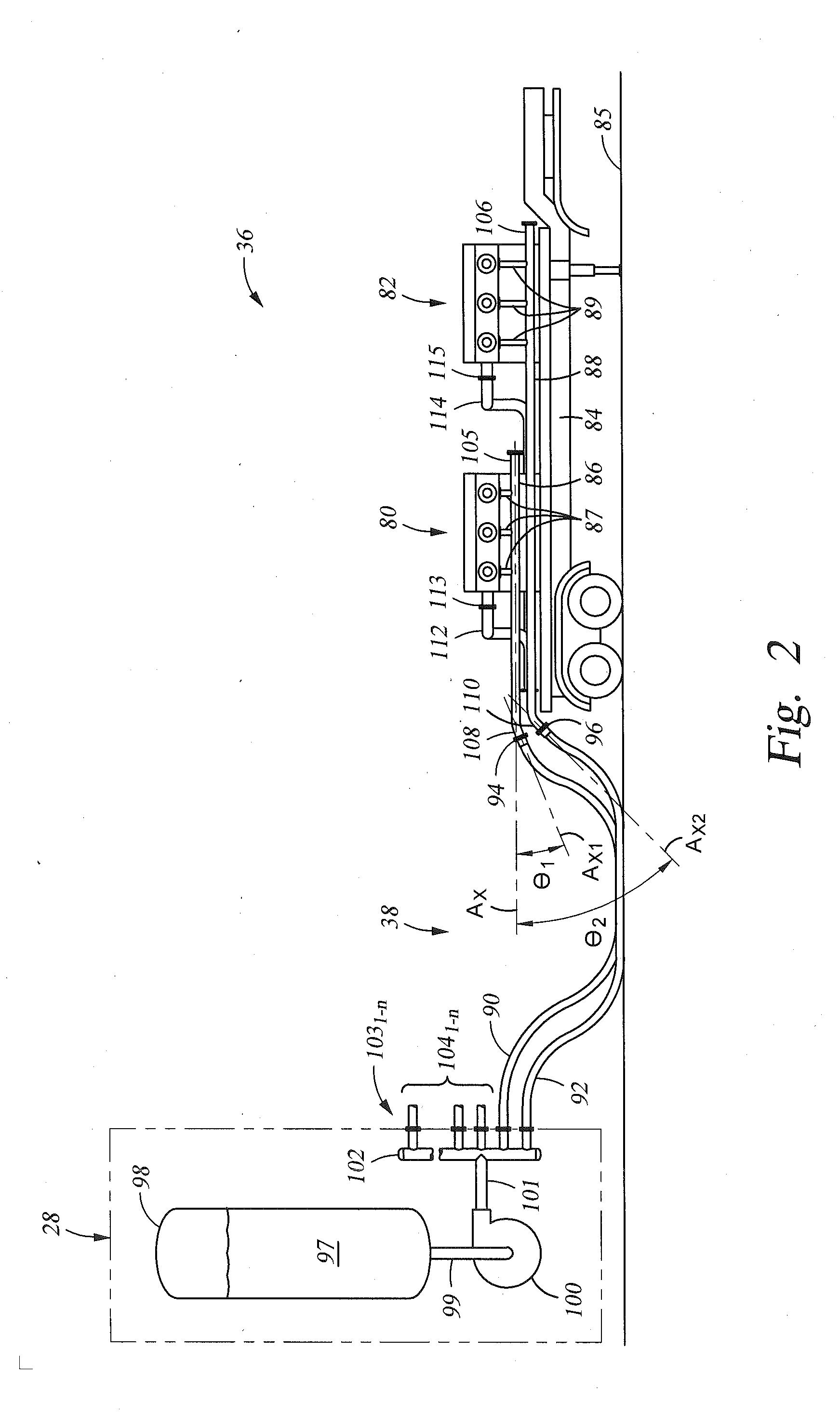
Suction and Discharge Lines for a Dual Hydraulic Fracturing Unit
a hydraulic fracturing unit and discharge line technology, applied in the direction of positive displacement liquid engine, fluid removal, borehole/well accessories, etc., can solve the problem of difficult connection for operations personnel to handl
- Summary
- Abstract
- Description
- Claims
- Application Information
AI Technical Summary
Benefits of technology
Problems solved by technology
Method used
Image

Examples
Embodiment Construction
[0015]The method and system of the present disclosure will now be described more fully hereinafter with reference to the accompanying drawings in which embodiments are shown. The method and system of the present disclosure may be in many different forms and should not be construed as limited to the illustrated embodiments set forth herein; rather, these embodiments are provided so that this disclosure will be thorough and complete, and will fully convey its scope to those skilled in the art. Like numbers refer to like elements throughout. In an embodiment, usage of the term “about” includes + / −5% of the cited magnitude. In an embodiment, usage of the term “substantially” includes + / −5% of the cited magnitude.
[0016]It is to be further understood that the scope of the present disclosure is not limited to the exact details of construction, operation, exact materials, or embodiments shown and described, as modifications and equivalents will be apparent to one skilled in the art. In the ...
PUM
 Abstract
Description
Claims
Application Information