
Portable head ct scanner

a ct scanner and portable head technology, applied in the field of xray imaging scanners, can solve the problems of difficult use of ct scanners elsewhere, limited use of ct scanners in hospitals or clinical settings, and large volume of ct scanners

Inactive Publication Date: 2016-11-10
TRIBO LABS
View PDF2 Cites 16 Cited by
  • Summary
  • Abstract
  • Description
  • Claims
  • Application Information

AI Technical Summary

Benefits of technology

The invention is about a portable head CT scanner that can be easily moved around in multiple containers. The scanner is attached to a rotating frame, which can be separated into different sections for easy transportation. The scanner's components are mounted on this frame, which also allows for easy disassembly and storage. Overall, this invention provides a convenient and portable solution for conducting head CT scans.

Problems solved by technology

In many instances CT scanners are limited to hospital or clinical settings.
Although the diagnostic information provided by CT scanners may be useful outside of such settings, there are difficulties in use of CT scanners elsewhere.
CT scanners are often relatively heavy, decreasing mobility of the scanners and some scanners may need to be mounted to solid foundations.
CT scanners generally require a sufficiently large aperture to allow for passage of a human body, or significant parts thereof, resulting in a size requirement that may be unsuitable for use in, or transport through, compact spaces and for transport through conventional doors.
Electrical power requirements for generating x-rays from an x-ray source are often significant, thereby often requiring access to utility line power sources.
In short, a variety of factors, for example weight, aperture size requirements, electrical power requirements, and storage and usage environment requirements impede the use of CT scanners outside of hospital and clinical settings.

Method used


Image

  • Portable head ct scanner
  • Portable head ct scanner
  • Portable head ct scanner

Examples


Embodiment Construction

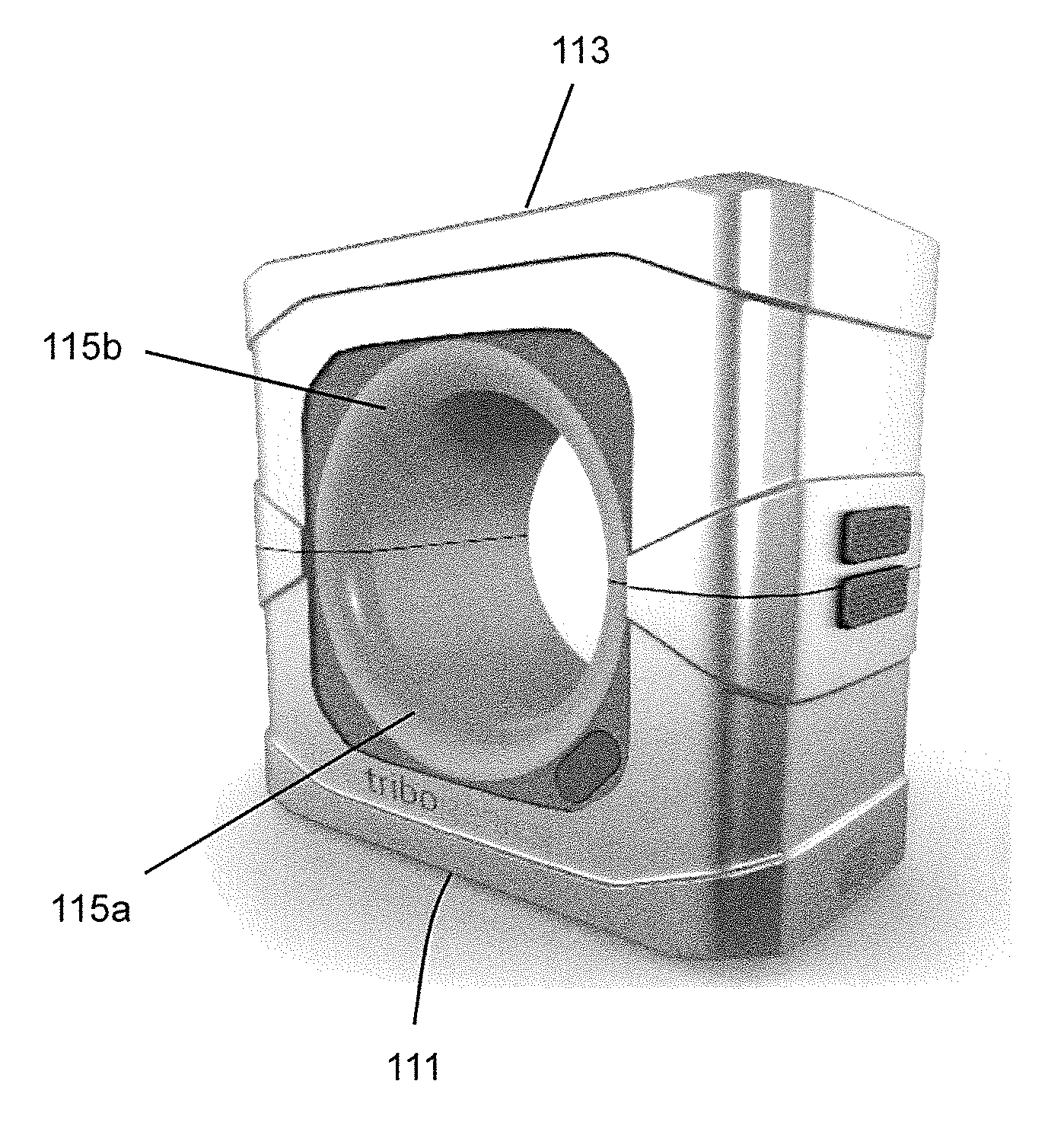
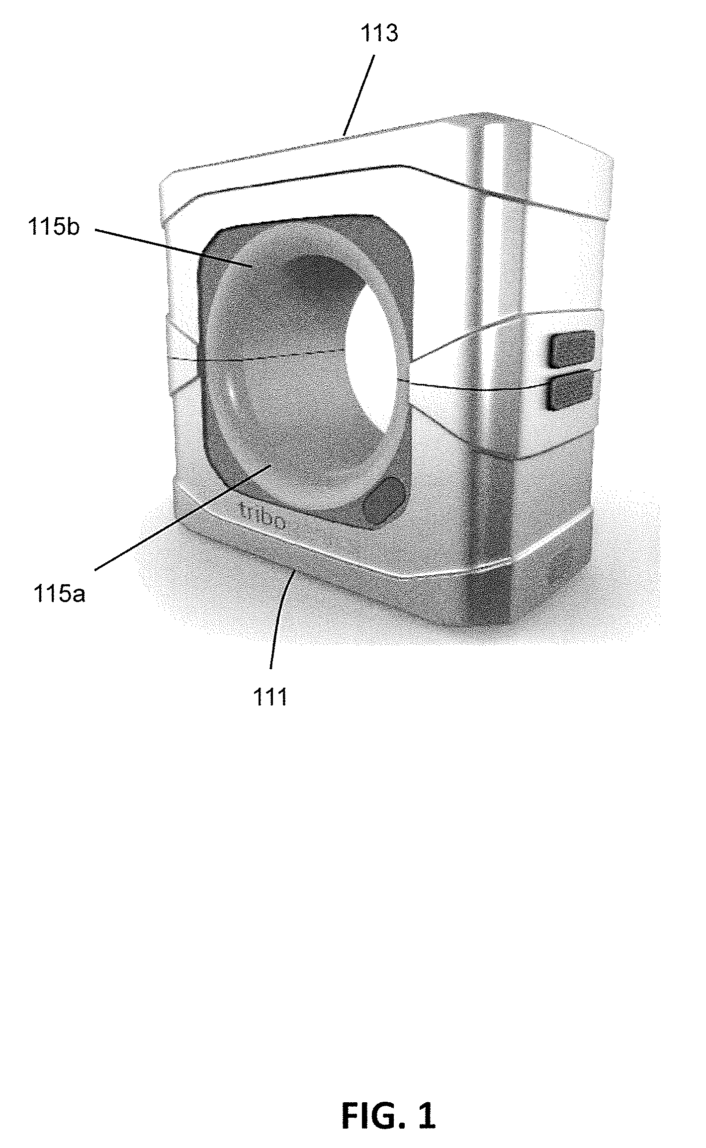
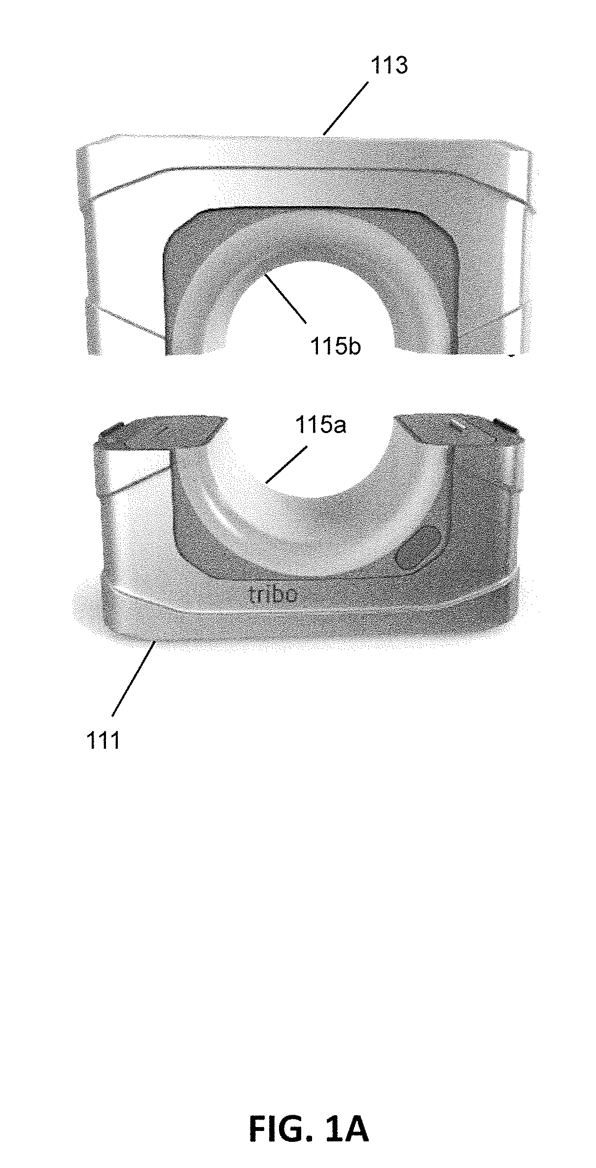
[0021]FIG. 1 illustrates a CT scanner in accordance with aspects of the invention. The CT scanner of FIG. 1 includes a first enclosure 111 and a second enclosure 113. Although two enclosures are shown in FIG. 1, in various embodiments the CT scanner may be comprised of more than two enclosures. An aperture extends through the CT scanner, with the aperture defined by arches 115a and 115b in each of the first enclosure 111 and second enclosure 113. In operation, a rotatable frame including a high energy radiation source and a high energy radiation detector rotates about the aperture within the first enclosure 111 and second enclosure 113. In same embodiment the high energy radiation source is an x-ray source, and the high energy radiation detector is an x-ray detector. In some embodiments the high energy radiation source is a gamma ray source.

[0022]FIG. 1A shows the CT scanner of FIG. 1 with the first enclosure 111 and the second enclosure 113 separated from one another. As may be see...


PUM


Abstract

A portable CT scanner may include a rotatable frame with separable portions. An x-ray source may be coupled to one portion of the rotatable frame, and an x-ray detector may be coupled to another portion of the rotatable frame. During storage and transportation, one portion of the rotatable frame may be housed in a first enclosure, and another portion of the rotatable frame may be housed in a second enclosure. When operation of the scanner is desired, the two enclosures may be connected, and / or the rotatable frame portions may be connected with the enclosures abutting one another, to allow for rotation of the rotatable frame about an aperture formed by the enclosures.

Description

CROSS-REFERENCE TO RELATED APPLICATION[0001]The present application is a continuation of U.S. patent application Ser. No. 14 / 219,846, filed Mar. 19, 2014, the disclosure of which is incorporated by reference herein.BACKGROUND OF THE INVENTION[0002]The present invention relates generally to x-ray imaging scanners, and more particularly to portable computer tomography (CT) scanners.[0003]CT scanners are commonly used in healthcare applications, generally for diagnostic purposes. CT scanners usually include an x-ray source and an x-ray detector. The x-ray source and the x-ray detector are generally positioned on a rotatable frame such that the x-ray source and the x-ray detector are generally on, or centered on, opposite sides of an aperture. In use, a patient is positioned at least partially in the aperture, and rotation of the frame allows for multiple images of the portion of the patient within the aperture. In some instances, the patient may also be moved through the aperture, allo...

Claims


Application Information

Patent Timeline
Patent Type & Authority Applications(United States)
IPC IPC(8): A61B6/03A61B6/00
CPCA61B6/035A61B6/4405A61B6/4411A61B6/501A61B6/40A61B6/42A61B6/56A61B6/032
Inventor CRAWFORD, CARLFOX, DALECAMARA, CARLOSRAUDA, ALDIS
Owner TRIBO LABS
Learn More