Power switching circuit and method for controlling same

a power switching circuit and power switching technology, applied in static indicating devices, instruments, cathode-ray tube indicators, etc., can solve the problems of uneven brightness of the same pixel over time, varies irregularly, and may not be uniform in the value of pixels at different locations, so as to achieve uniform brightness. , the effect of uniform brightness

Active Publication Date: 2016-11-17
SILICON WORKS CO LTD
View PDF3 Cites 2 Cited by
  • Summary
  • Abstract
  • Description
  • Claims
  • Application Information

AI Technical Summary

Benefits of technology

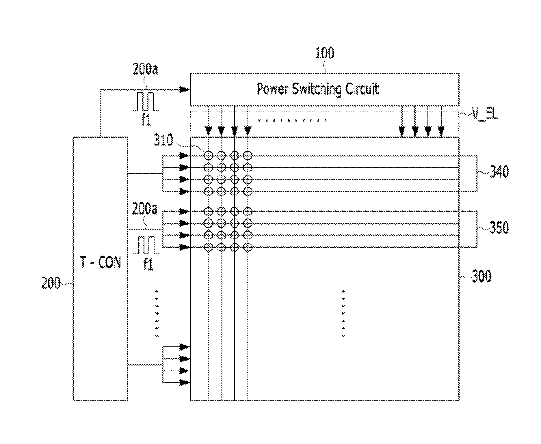
[0021]An object of the present invention is to divide pixels, constituting the screen of a display device, into rows, columns, blocks, or sub-region

Problems solved by technology

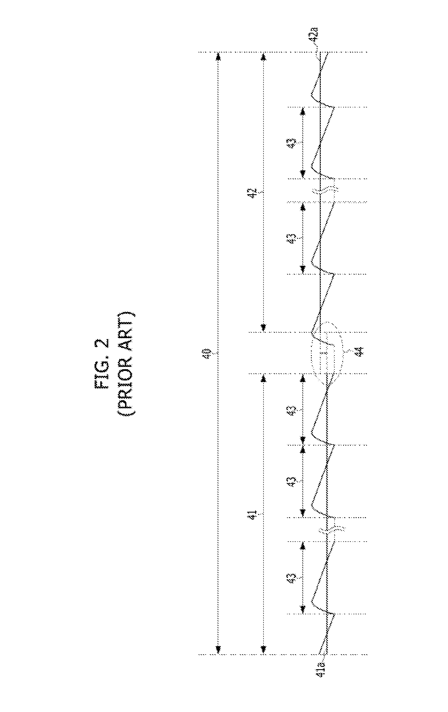
Furthermore, there is concern that the pixels that emit light during the first time interval 41 may receive an average value, different from the first average value 41a, as the effective output voltage V_EL in a subsequent time interval (not shown) in which the pixels are sequentially operated, and thus there is concern

Method used


Image

  • Power switching circuit and method for controlling same
  • Power switching circuit and method for controlling same
  • Power switching circuit and method for controlling same

Examples


Embodiment Construction

[0040]The terms used herein will be used merely to describe embodiments, and are not intended to limit the present invention. A singular form may include a plural form unless otherwise defined. The terms, including “comprise,”“includes,”“comprising,”“including” and their derivatives, specify the presence of described features, numbers, steps, operations, components, parts and / or combinations thereof, and do not exclude the possibility of the presence or addition of one or more other features, numbers, steps, operations, components, parts, and / or combinations thereof.

[0041]Unless otherwise defined herein, all terms, including technical or scientific terms used herein, have the same meanings as commonly understood by those skilled in the art to which the present invention pertains. Terms, such as those defined in commonly used dictionaries, should be interpreted as having meanings that are consistent with their meanings in the context of the specification and relevant art, and should...


PUM


Abstract

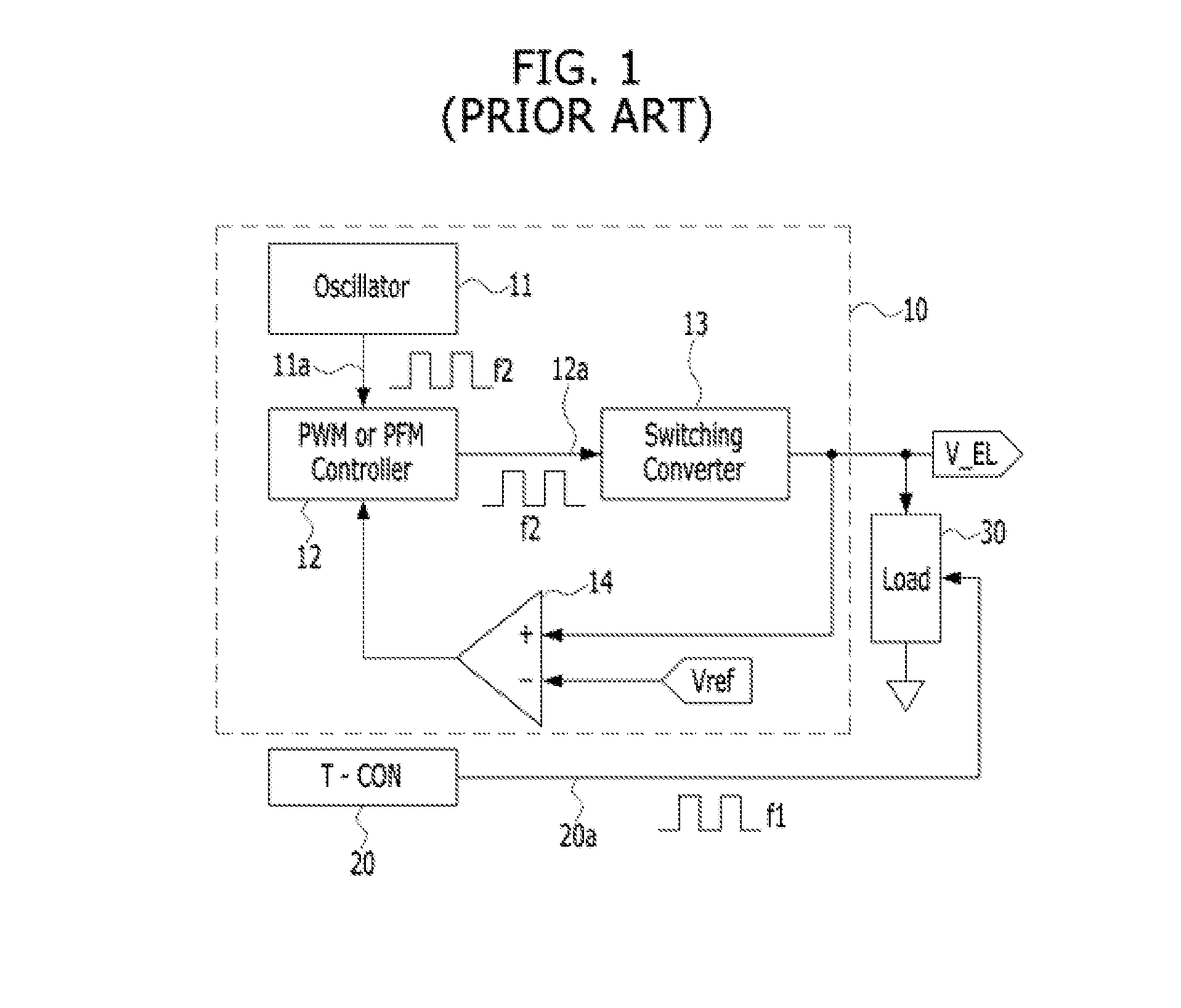
A power switching circuit and a method for controlling the same are disclosed herein. The power switching circuit includes a frequency control circuit, a pulse modulation circuit, and a switching convertor. The frequency control circuit receives a first reference signal driving a load, from a timing controller, and generates a second reference signal based on the first reference signal. The pulse modulation circuit generates a pulse control signal by performing pulse width modulation (PWM) or pulse frequency modulation (PFM) on the second reference signal. The switching convertor generates the voltage of output power by switching a switching element connected to the output power, in response to the pulse control signal. The pulse control signal is synchronized with the first reference signal driving the load.

Description

CROSS-REFERENCE TO RELATED APPLICATION[0001]This application claims under 35 U.S.C. §119(a) the benefit of Korean Application No. 10-2015-0067371 filed on May 14, 2015, which is incorporated herein by reference.TECHNICAL FIELD[0002]The present invention relates generally to technology for maintaining an output voltage, to be provided to a load, at a constant level using a switching converter circuit, and more particularly to a switching converter circuit that is capable of maintaining the brightness of an overall screen at a uniform level when an array of pixels on a display screen is driven, and technology for controlling the same.BACKGROUND ART[0003]Thin-Film Transistor Liquid Crystal Displays (TFT-LCDs), Organic Light Emitting Displays (OLEDs), etc. are being currently widely used as display devices for TVs, computers or mobile phones. In such a display device, the array of pixels of a TFT-LCD or an OLED scans data in response to signals that are sequentially applied, and then se...

Claims


Application Information

Patent Timeline
IPC IPC(8): G09G5/10
CPCG09G5/10G09G2310/08G09G2320/0233G09G3/2096G09G3/2014G09G2310/0218G09G3/2022
Inventor SHIN, YOON SOOHAN, JI WOONGLEE, DEA HWAN
Owner SILICON WORKS CO LTD
Why Eureka
Try Eureka