Mobile Phone Antenna System

a mobile phone and antenna technology, applied in the field of mobile communication, can solve the problems of increasing the design difficulty of antennas and poor isolation between several antenna structures

Inactive Publication Date: 2016-12-01
AAC TECH PTE LTD
View PDF6 Cites 15 Cited by
  • Summary
  • Abstract
  • Description
  • Claims
  • Application Information

AI Technical Summary

Problems solved by technology

These means will affect the overall appearance of the metal cover, also increase the design

Method used


Image

  • Mobile Phone Antenna System
  • Mobile Phone Antenna System
  • Mobile Phone Antenna System

Examples


Embodiment Construction

[0009]The present invention will hereinafter be described in detail with reference to an exemplary embodiment. To make the technical problems to be solved, technical solutions and beneficial effects of present disclosure more apparent, the present disclosure is described in further detail together with the figures and the embodiment. It should be understood the specific embodiment described hereby is only to explain this disclosure, not intended to limit this disclosure.

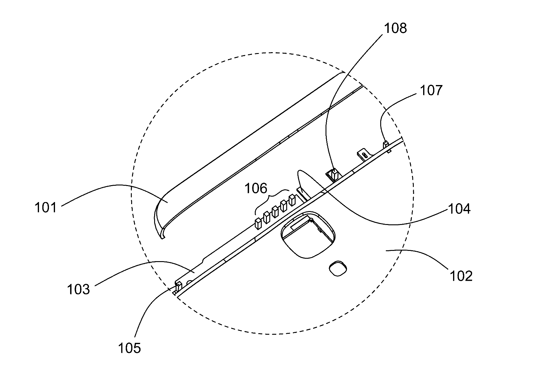
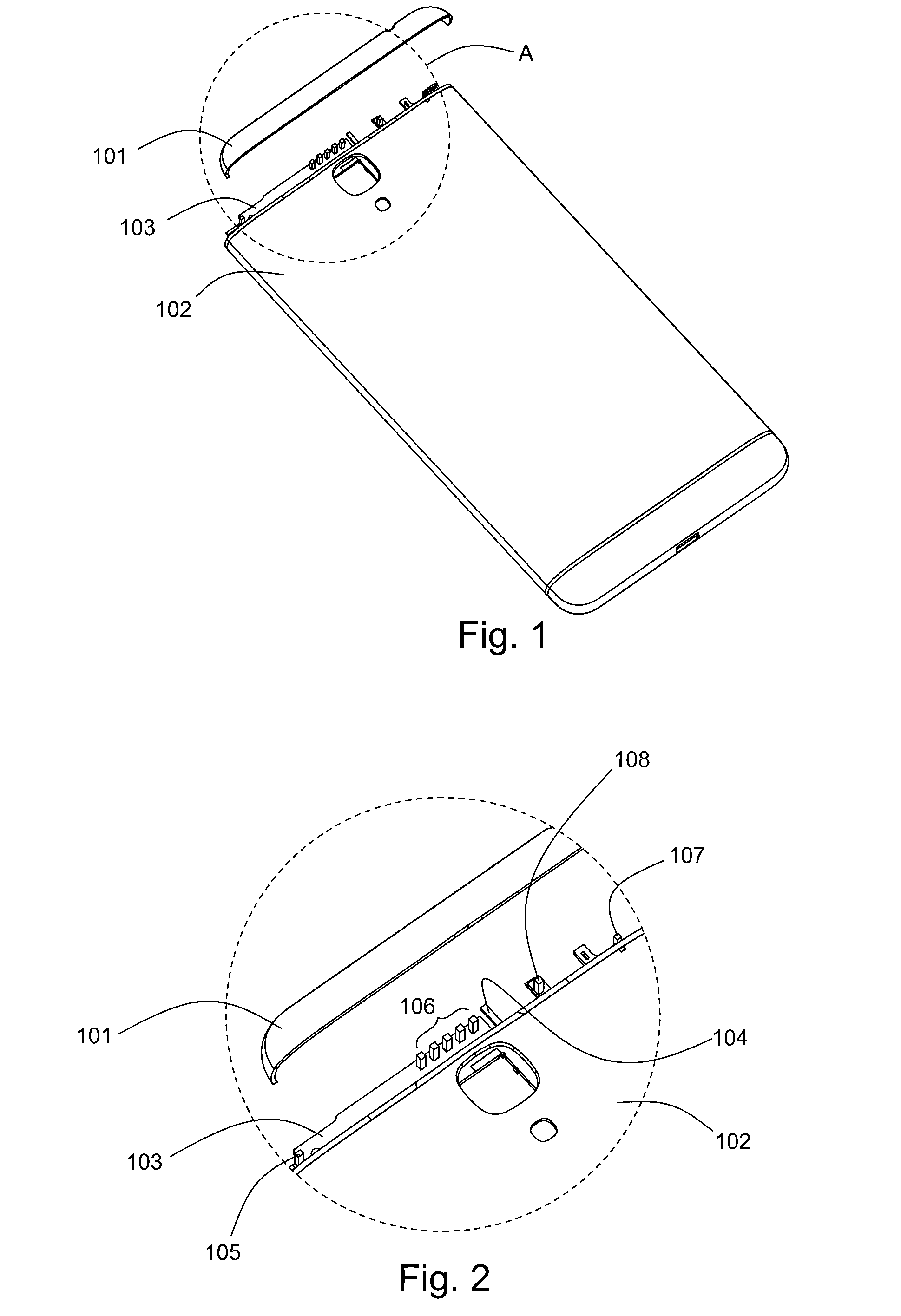
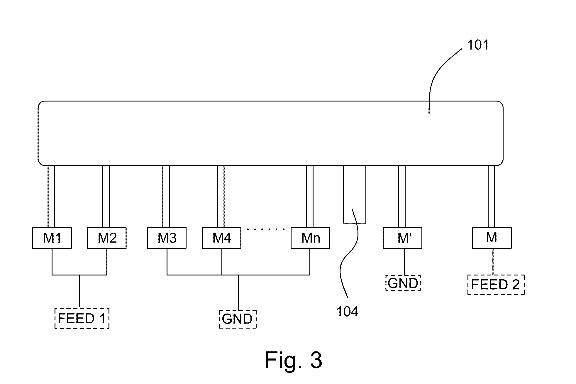
[0010]As shown in FIG. 1, a mobile phone antenna system 100, in accordance with an exemplary embodiment of the present disclosure, includes a metal rear cover, a circuit board 103, a first antenna module and a second antenna module electrically connected with the circuit board103. The metal rear cover includes a top cover 101, a middle cover 102 keeping a distance from the top cover 101, and a connector 104 used for electrically connecting the top cover 101 and the middle cover 102. The circuit board 103 is provided ...


PUM


Abstract

A mobile phone antenna system includes a metal rear cover, a circuit board, a first antenna module and a second antenna module connected electrically with the circuit board. The metal rear cover includes a top cover, a middle cover with a distance from the top cover, and a connector used for connecting electrically the top cover and the middle cover. The circuit board is provided with several grounding points. The top cover takes the connector as dividing point. The first antenna module and the second antenna module are connected electrically with the top cover at one side of the connector. A number of second match circuits are connected electrically with the grounding points, and the mobile phone antenna system has better adjusting ability.

Description

FIELD OF THE INVENTION[0001]The present disclosure relates to mobile communication field, particular to a mobile phone antenna system.DESCRIPTION OF RELATED ART[0002]With progressive development of mobile phone, tablet and other mobile devices, the requirement on the appearance of mobile terminal devices is increasingly high. Mobile phone with a metal housing, because of its texture and wear resistance, is favored by the majority of consumers.[0003]The mobile phone with relevant technologies usually includes a metal housing and several antenna structures in the metal housing. These antenna structures located in the metal housing take usually metal ring or metal cap on the metal housing as the radiator of the antenna. The antenna covers more frequency bands by means of opening more slits on the metal cover or increasing antenna's quantity. These means will affect the overall appearance of the metal cover, also increase the design difficulty of antenna. The isolation between several a...

Claims


Application Information

Patent Timeline
IPC IPC(8): H01Q1/24H01Q5/335
CPCH01Q5/335H01Q1/243H01Q5/328H01Q5/35
Inventor WU, XIAOPUCHEN, YONGLI
Owner AAC TECH PTE LTD
Why Eureka
Try Eureka