Eccentric heat dispensing fans

a fan and fan body technology, applied in the direction of machines/engines, solid-state devices, waterborne vessels, etc., can solve the problems of base plate shaking, back-pressure, and air volume sucked from the opening in the top of the hub and the volume of air sucked from the opening in the bottom of the hub not being balanced,

Inactive Publication Date: 2005-04-12
LIN SHUEEI MUH +1
View PDF3 Cites 44 Cited by
  • Summary
  • Abstract
  • Description
  • Claims
  • Application Information

AI Technical Summary

Benefits of technology

The present invention will become more obvious from the following description when taken in connection with the accompa...

Problems solved by technology

However, the volume of air sucked from the opening in the top of the hub and the volume of air sucked from the openings in the bottom of the hub are not balanced so that the base plate shakes during operation.
The base plate stops the...

Method used


Image

  • Eccentric heat dispensing fans
  • Eccentric heat dispensing fans
  • Eccentric heat dispensing fans

Examples


Embodiment Construction

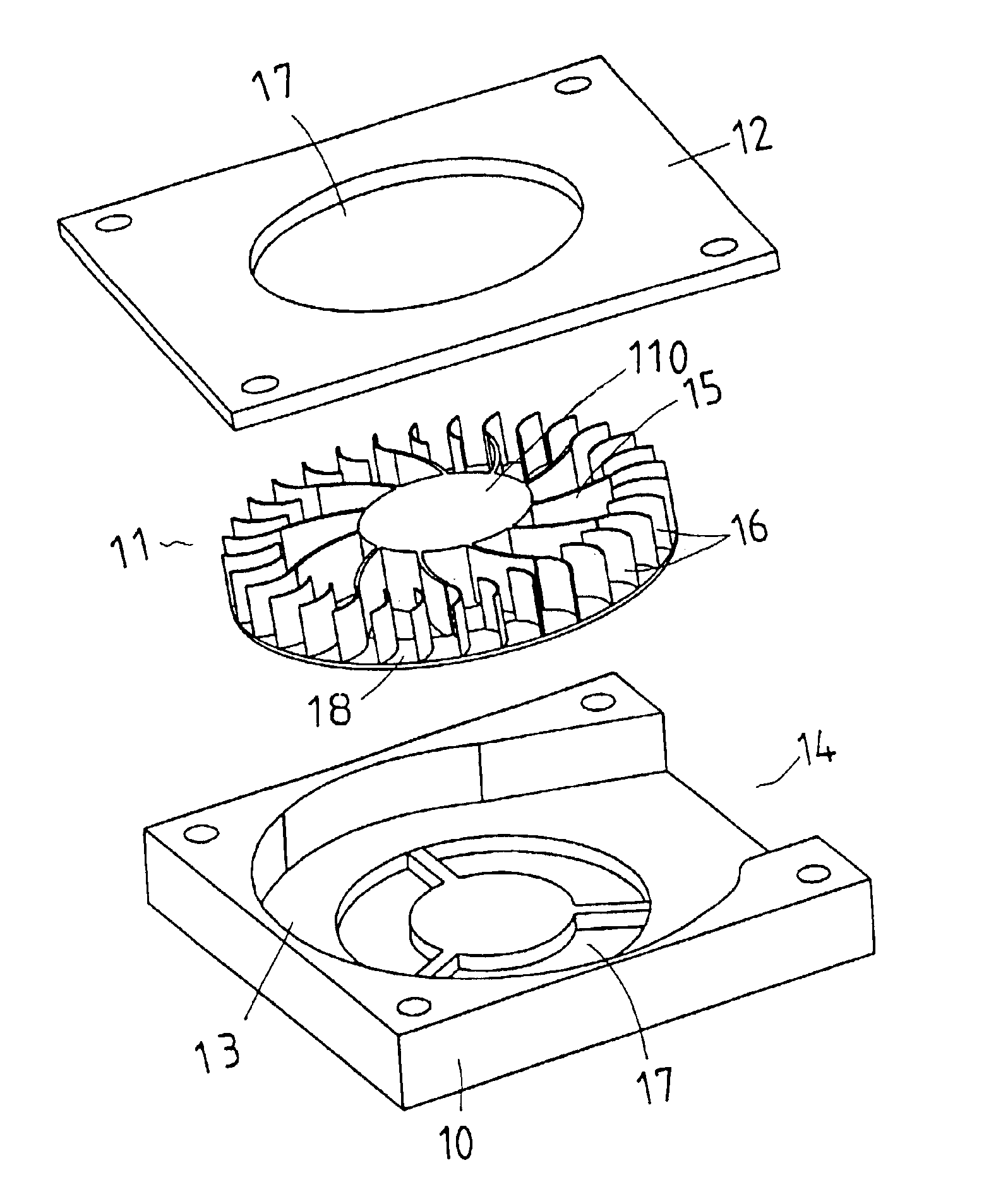
Referring to FIGS. 4 to 6, the heat dispensing fan of the present invention comprises a hub 10 having a recess 13 defined in a top thereof and communicating with a side outlet 14. Three apertures 17 are defined through the hub 10 and communicate with the recess 13.

A fan member 11 has a ring-shaped base plate 18 and a protrusion 110 extends from a center of a top of the base plate 18. A plurality of first curve blades 15 extend from the protrusion 110 and located on a top of the base plate 18. A plurality of second curve blades 16 are located on the top of the base plate 18 and each first curve blade 15 is connected to one of the second curve blades 16. A top cap 12 is connected to the hub 10 and having a hole 17 defined therethrough.

Air can be sucked from the hole 17 in the top cap 12 and the apertures 17. Because the blades 15, 16 are curved so that the air flow can smoothly flow via the curve surface of the blades 15, 16 and out from the side outlet 14. The ring-shaped base plate ...


PUM


Abstract

A heat dispensing fan includes a hub having a recess defined in a top thereof so as to receive a fan member therein. The recess communicates with a side outlet in the hub and apertures defined through the hub. The fan member has a ring-shaped base plate and a protrusion extends from a center of a top of the base plate. A plurality of first curve blades extends from the protrusion and a plurality of second curve blades are located on the top of the base plate. Each first curve blade is connected to one of the second curve blades. A top cap is connected to the hub and has a hole defined therethrough.

Description

FIELD OF THE INVENTIONThe present invention relates to an eccentric heat dispensing fan used for dispensing heat from CPU and includes inner blades and outer blades so as to increase the volume of the air blow to effectively dispense heat away from the CPU.BACKGROUND OF THE INVENTIONA conventional heat dispensing fan is shown in FIG. 1 and generally includes a base plate with a plurality of blades thereon. FIGS. 2 and 3 show a developed version of the heat dispensing fan which includes a base plate with a plurality of blades on both sides of the base plate, the base is rotatably received in a hub which includes a top opening, two bottom openings and a side outlet. When the base plate is rotated, air is sucked in the hub via the openings and then flows out from the side outlet. However, the volume of air sucked from the opening in the top of the hub and the volume of air sucked from the openings in the bottom of the hub are not balanced so that the base plate shakes during operation....

Claims


Application Information

Patent Timeline
IPC IPC(8): F04D29/28F04D29/30H01L23/467H01L23/34
CPCF04D29/281F04D29/30H01L23/467H01L2924/0002H01L2924/00
Inventor LIN, SHUEEI-MUHLEE, SEN-YUNG
Owner LIN SHUEEI MUH
Why Eureka
Try Eureka