
Inflatable parachute airbag system

a parachute and airbag technology, applied in the field of airborne object protection, can solve the problems of aerial vehicles generally falling towards the ground, inability to correct inflight failures before the vehicle, and still significant cos

Inactive Publication Date: 2016-12-22
DMATERIAL IP LLC
View PDF3 Cites 25 Cited by
  • Summary
  • Abstract
  • Description
  • Claims
  • Application Information

AI Technical Summary

Benefits of technology

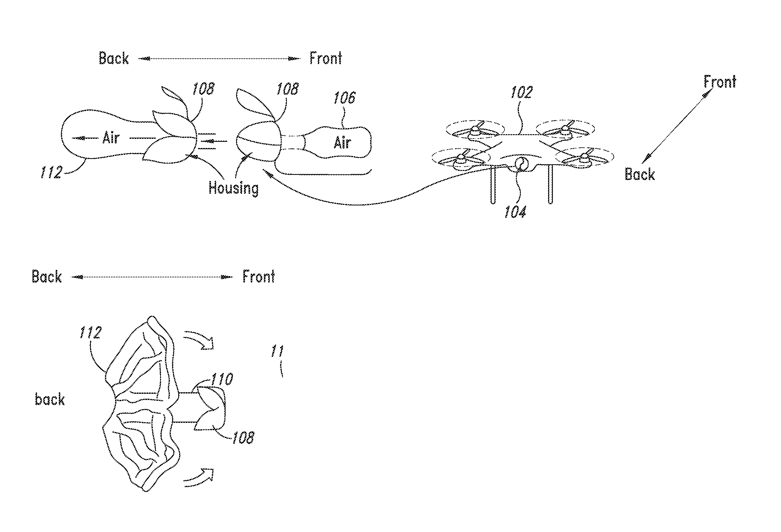
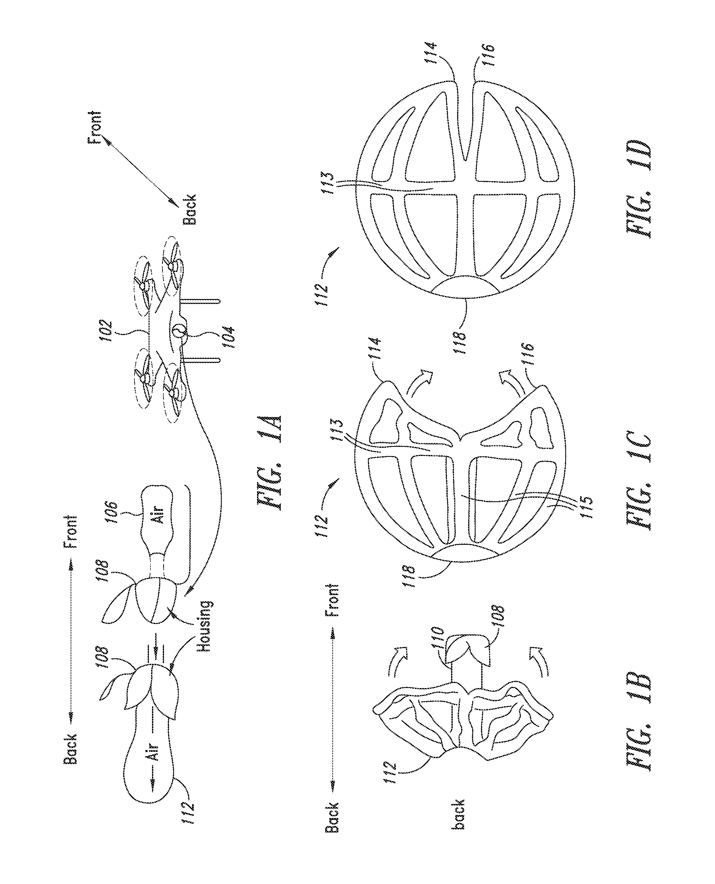
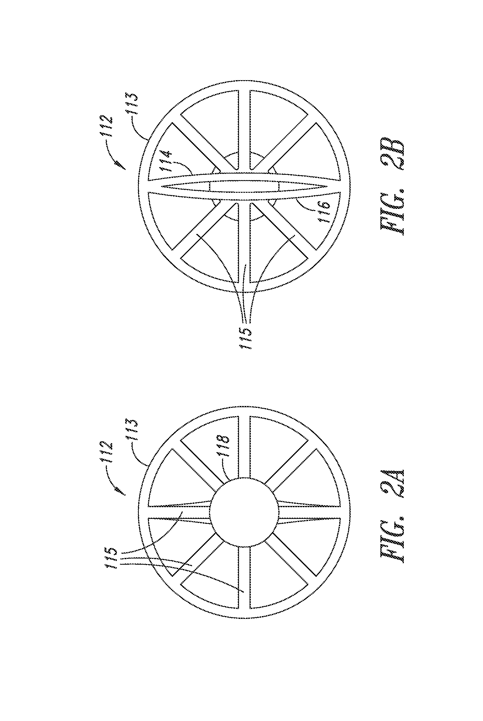
This patent describes a system and method for preventing an aerial vehicle from crashing or losing control during an uncontrolled descent. The system includes an inflatable cage that is attached to the aerial vehicle and can be deployed in case of an emergency. The cage has support tubes and a perimeter tube that can be filled with air to inflate the cage using a fill tube. The cage can be connected to a second set of support tubes that can encase the aerial vehicle. The system also includes an enclosure made of parachute material to create drag and reduce the velocity of the aerial vehicle. Additionally, weight distribution straps are attached between the aerial vehicle and the cage or support tubes to distribute the load and further stabilize the vehicle. Overall, this system can provide a safe and effective way to prevent accidents and protect aerial vehicles in the event of an emergency.

Problems solved by technology

Although these vehicles are more affordable than in previous years, their cost is still significant enough to warrant some protection against damage resulting from an in-air failure.
When an inflight failure occurs, aerial vehicles generally begin to plummet towards the ground.
Inflight failures generally cannot be corrected before the vehicle hits the ground due to low flying altitudes or non-recoverable failures (e.g., a dead battery).
Such crashes often leave the vehicle with major, or even irreparable, damage.
Unfortunately, many failures result in sporadic and uncontrollable movement of the vehicle such that parachutes cannot be properly deployed, often resulting in the aerial vehicle crashing despite an attempt to deploy a traditional parachute system.

Method used


Image

  • Inflatable parachute airbag system
  • Inflatable parachute airbag system
  • Inflatable parachute airbag system

Examples


Embodiment Construction

[0034]In the following description, certain specific details are set forth in order to provide a thorough understanding of various disclosed implementations. However, one skilled in the relevant art will recognize that the present disclosed implementations may be practiced without one or more of these specific details or with other methods, components, materials, etc. In other instances, well-known structures or components or both that are associated with the environment of the present disclosure have not been shown or described in order to avoid unnecessarily obscuring descriptions of the implementations.

[0035]Unless the context requires otherwise, throughout the specification and claims that follow, the word “comprise” and variations thereof, such as “comprises” and “comprising” are to be construed in an open inclusive sense, that is, as “including, but not limited to.” The foregoing applies equally to the words “including” and “having.”

[0036]Reference throughout this description ...


PUM


Abstract

A system and method for resisting an uncontrolled descent or uncontrolled flight condition of an aerial vehicle. The system includes a control system, sensors, an inflation device, and a deployable, inflatable assembly. The control system detects an uncontrolled condition using the sensors, and subsequently initiates the inflation device to inflate the inflatable assembly. The assembly includes an inflatable cage stored on and deployed from the aerial vehicle upon detection of an uncontrolled condition. The inflatable cage includes a hub, a perimeter tube, and support tubes connected between the hub and perimeter tube. Fill tubes enable inflation of the support and perimeter tubes. The assembly includes a parachute-material enclosure connected to the inflatable cage and structured to create drag to reduce a velocity of the aerial vehicle when the inflatable assembly is deployed. The assembly includes weight distribution straps physically coupled between the vehicle and the enclosure or inflatable cage.

Description

BACKGROUND[0001]Technical Field[0002]The present disclosure pertains to airborne object protection and, more particularly, to providing a system having a deployable assembly that attaches to the airborne object and when deployed provides parachute- and airbag-like properties to safely return the airborne object to the ground.[0003]Description of the Related Art[0004]Recent advancements in drone and personal-unmanned aerial vehicle technology have greatly reduced the cost of these vehicles and made them readily available to the general public. Although these vehicles are more affordable than in previous years, their cost is still significant enough to warrant some protection against damage resulting from an in-air failure.[0005]When an inflight failure occurs, aerial vehicles generally begin to plummet towards the ground. Inflight failures generally cannot be corrected before the vehicle hits the ground due to low flying altitudes or non-recoverable failures (e.g., a dead battery). S...

Claims


Application Information

Patent Timeline
Patent Type & Authority Applications(United States)
IPC IPC(8): B64D17/72B64C39/02B64D17/80
CPCB64D17/72B64C2201/185B64C39/024B64D17/80B64D25/00B64D2201/00B64U10/13B64U70/83B64U50/19
Inventor ERICKSON, ALAN JAMAL
Owner DMATERIAL IP LLC
Learn More