Antenna device and electronic apparatus
- Summary
- Abstract
- Description
- Claims
- Application Information
AI Technical Summary
Benefits of technology
Problems solved by technology
Method used
Image

Examples
first preferred embodiment
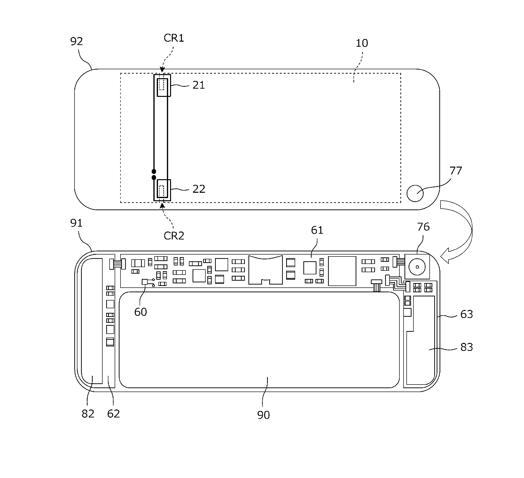
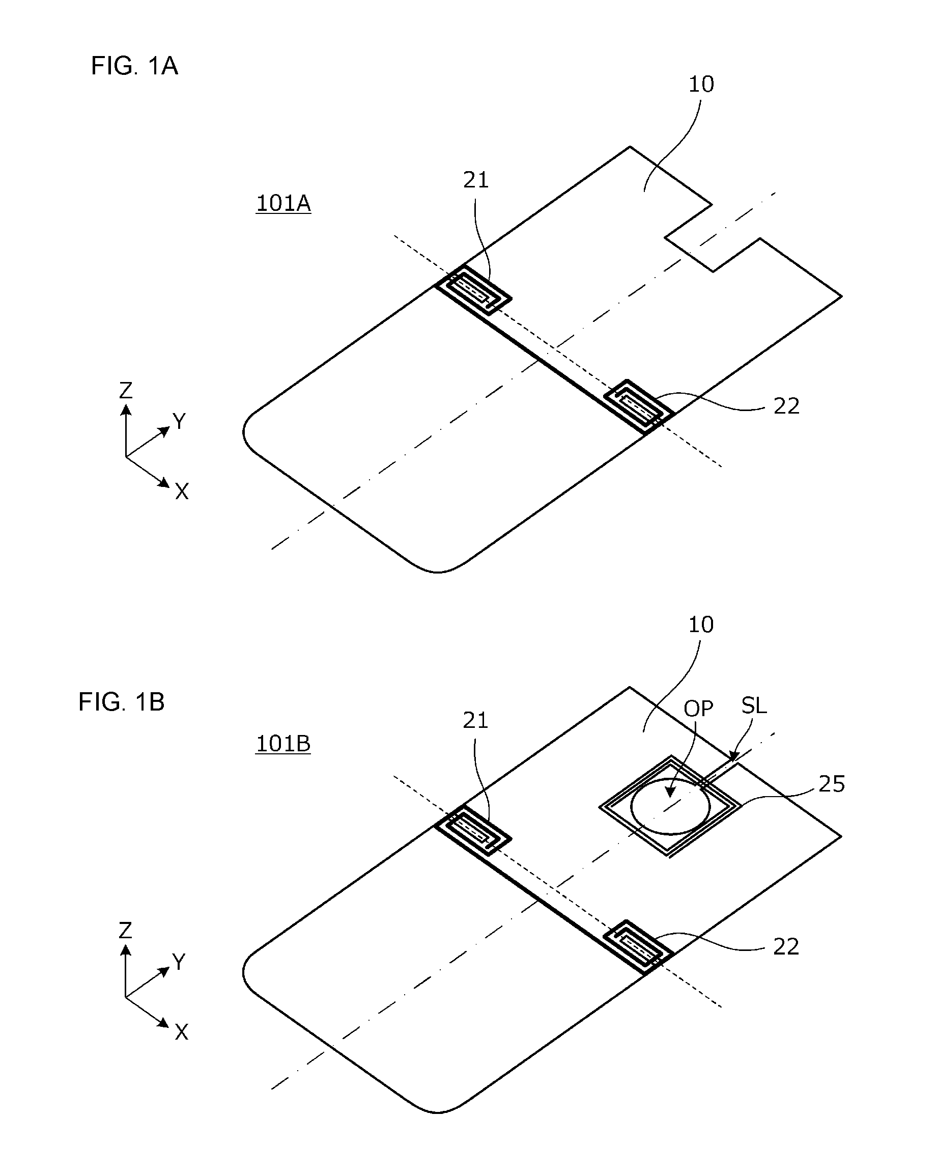
[0039]FIGS. 1A and 1B are perspective views of antenna devices 101A and 101B according to a first preferred embodiment of the present invention. First, the antenna device 101A will be mainly described. The antenna device 101A includes two coil conductors 21 and 22 each including a coil opening and a planar conductor 10. The planar conductor 10 is, for example, a metal portion of a casing of an electronic apparatus. Each of the coil conductors 21 and 22 is disposed at an edge portion of the planar conductor 10 in a state of having a winding axis in a normal direction of the planar conductor 10. The planar conductor 10 has a symmetry center line shown by an alternate long and short dash line, and the coil conductors 21 and 22 are disposed at positions which are symmetrical about the center line of the planar conductor 10. The planar conductor is a conductive component including at least a portion which extends planarly, and may be a surface of a curved surface shape or a cubic shape, ...
second preferred embodiment
[0059]FIG. 5A is a plan view of an antenna device 102 according to a second preferred embodiment of the present invention, and FIG. 5B is a cross-sectional view taken along an alternate long and short dash line in FIG. 5A. Magnetic sheets 51 and 52 are attached to the power supply coils 41 and 42 at the positions where the coil conductors 21 and 22 are provided. That is, the magnetic sheets 51 and 52 cover portions of the cutout-shaped portions CR1 and CR2 in a plan view.
[0060]Each of the magnetic sheets 51 and 52 is a ferrite sheet, and is a sintered magnetic ferrite with a sheet shape or a ferrite resin sheet in which magnetic ferrite powder is dispersed in a resin material.
[0061]Since the magnetic sheets 51 and 52 cover portions of the cutout-shaped portions CR1 and CR2 in a plan view as described above, the cutout-shaped portions CR1 and CR2 are magnetically shielded by the magnetic sheets 51 and 52, so that unnecessary radiation is significantly reduced or prevented. In additio...
third preferred embodiment
[0062]FIG. 6 is a plan view of an antenna device 103 according to a third preferred embodiment of the present invention. The coil conductors 21 and 22 are each patterned on a flexible board. Unlike the first and second preferred embodiments, in the present preferred embodiment, no cutout-shaped portion is provided in the planar conductor 10.
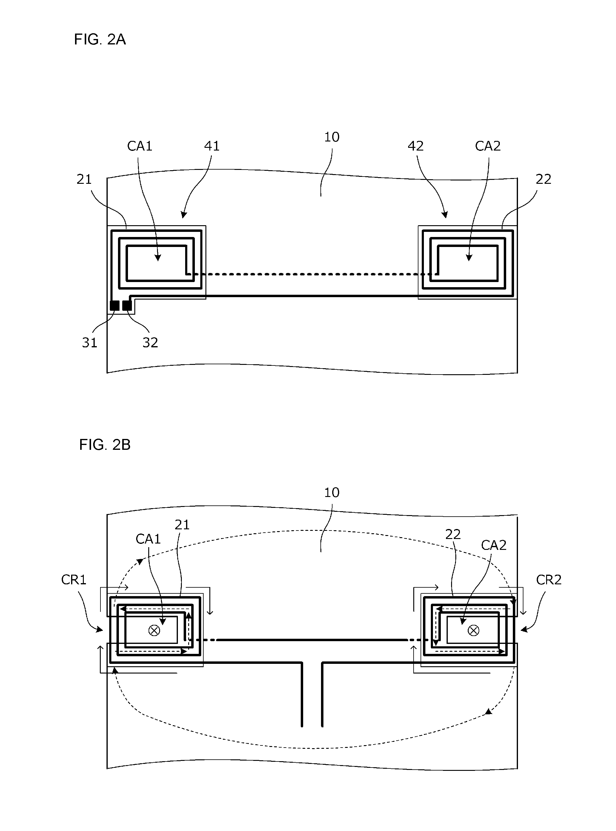
[0063]As shown in FIG. 6, the planar conductor 10 includes two opposing sides, and the coil conductors 21 and 22 are disposed with respect to the planar conductor 10 such that portions of the coil conductors 21 and 22 overlap the planar conductor 10, and portions of the coil openings CA1 and CA2 do not overlap the planar conductor 10.
[0064]In the case where the antenna device 103 defines and functions as a transmitting antenna, when a current flows through the coil conductors 21 and 22 in a direction shown by solid arrows in FIG. 6, a current shown by a dashed arrow is induced in the planar conductor 10. In the case where the antenna device 103 d...
PUM
 Abstract
Description
Claims
Application Information
 - R&D Engineer
- R&D Manager
- IP Professional
- Industry Leading Data Capabilities
- Powerful AI technology
- Patent DNA Extraction
Browse by: Latest US Patents, China's latest patents, Technical Efficacy Thesaurus, Application Domain, Technology Topic.
© 2024 PatSnap. All rights reserved.Legal|Privacy policy|Modern Slavery Act Transparency Statement|Sitemap