Compound engine assembly with direct drive of generator

a technology of engine assembly and generator, applied in the direction of machines/engines, electric generator control, energy-efficient board measures, etc., can solve the problems of added weight and complexity of ground-based apus, which may not be compatible with aircraft applications

Active Publication Date: 2016-12-29
PRATT & WHITNEY CANADA CORP
View PDF10 Cites 18 Cited by
  • Summary
  • Abstract
  • Description
  • Claims
  • Application Information

AI Technical Summary

Problems solved by technology

Known ground-based APUs typically include added weight and complexity which may not be compatible with use in aircraft applications.

Method used


Image

  • Compound engine assembly with direct drive of generator
  • Compound engine assembly with direct drive of generator
  • Compound engine assembly with direct drive of generator

Examples


Embodiment Construction

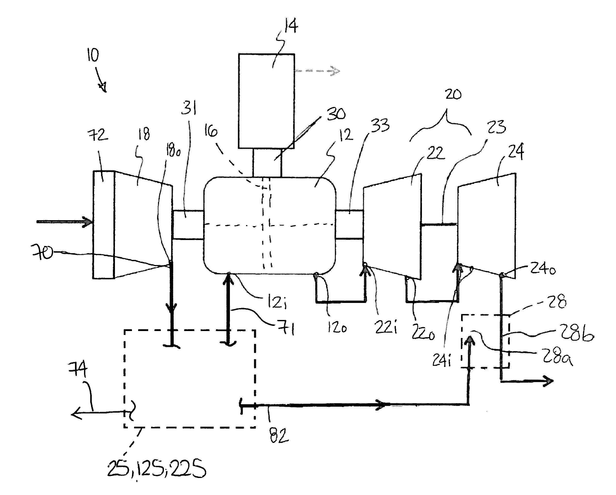
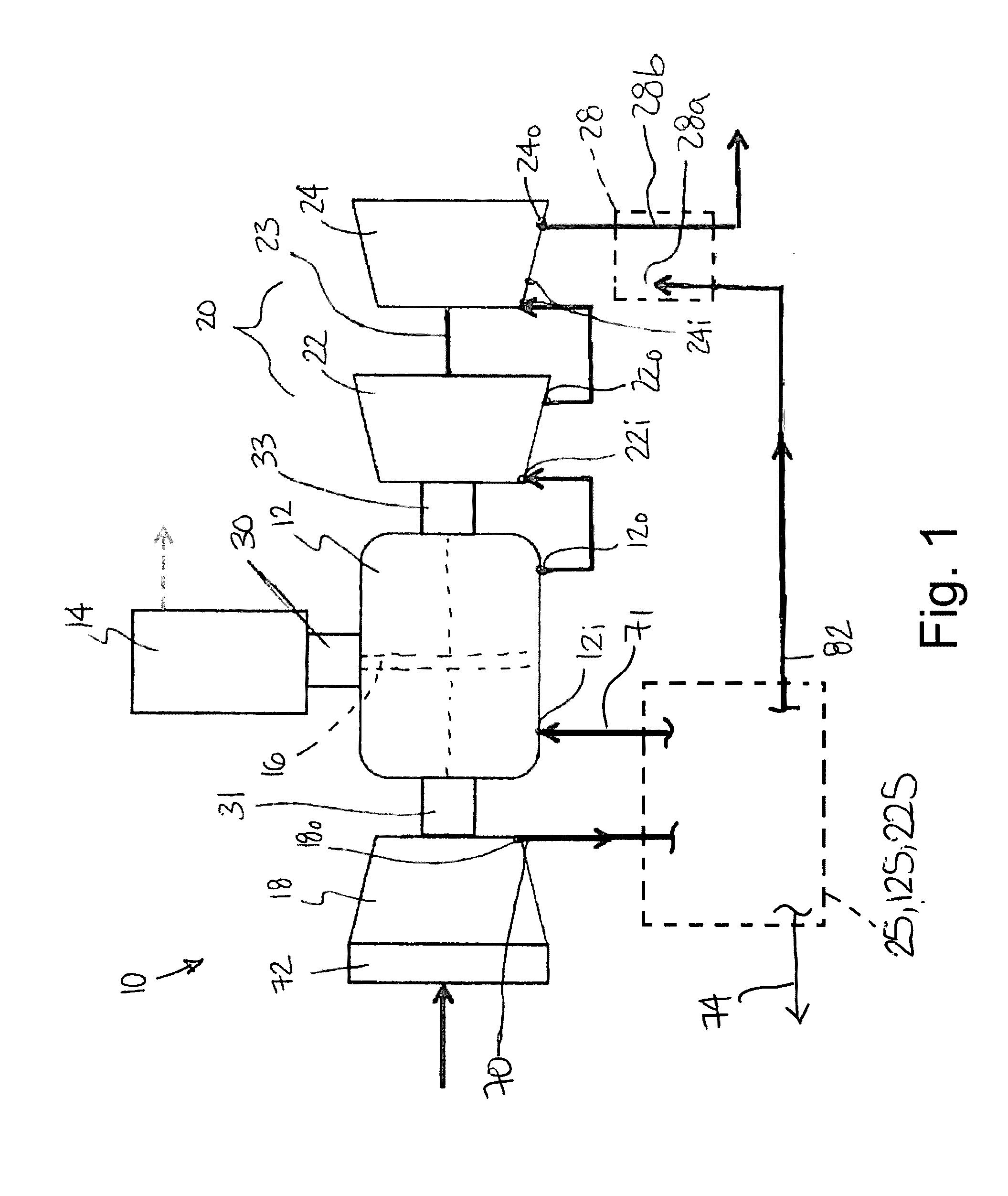
[0016]Referring to FIG. 1, a compound engine assembly 10 is schematically shown. The compound engine assembly 10 is particularly, although no exclusively, suitable for use as an airborne auxiliary power unit (APU). The compound engine assembly 10 includes an engine core 12 having an engine shaft 16 driving a load, shown here as a generator, for example to provide electrical power to an aircraft. Other possible loads may include, but are not limited to, a drive shaft, accessories, rotor mast(s), a compressor, or any other type of load or combination thereof. The compound engine assembly 10 further includes a compressor 18, a turbine section 20 compounding power with the engine core 12 and in driving engagement with the compressor 18 and generally including a first stage turbine 22 and a second stage turbine 24, and a flow distribution assembly 25, 125, 225, examples of which will be described further below.

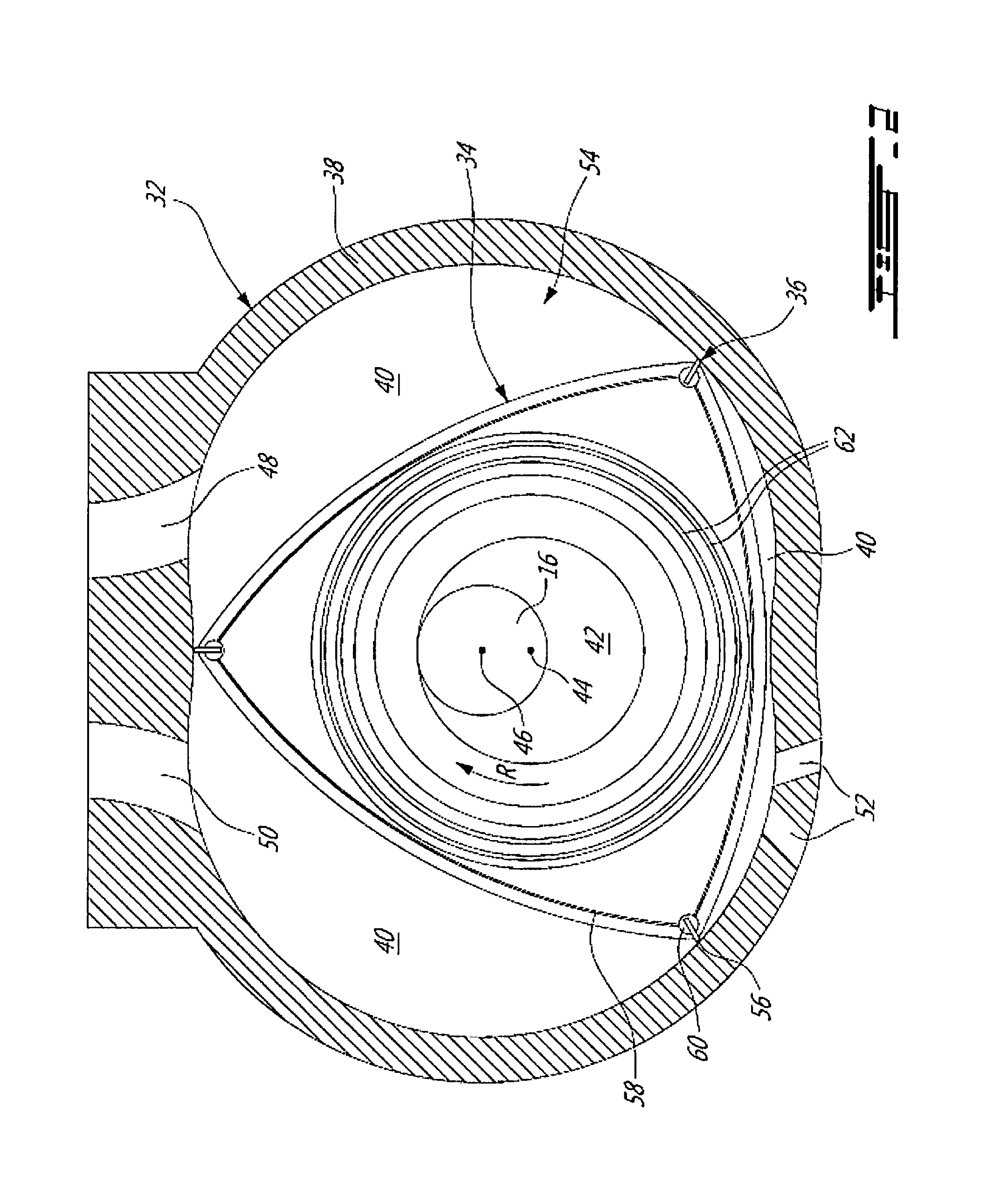
[0017]In a particular embodiment, the engine core 12 includes one or more rota...


PUM


Abstract

A compound engine assembly for use as an aircraft auxiliary power unit, having an engine core including internal combustion engine(s) in driving engagement with an engine shaft, a generator having a generator shaft directly engaged to the engine shaft such as to be rotatable at a same speed, a compressor having an outlet in communication with the engine core inlet, and a turbine section having an inlet in communication with the engine core outlet and configured to compound power with the engine core. The turbine section may include a first stage turbine having an inlet in communication with the engine core outlet, and a second stage turbine having an inlet in communication with the first stage turbine outlet. A method of providing electrical power to an aircraft is also discussed.

Description

TECHNICAL FIELD[0001]The application related generally to compound engine assemblies and, more particularly, to such compound engine assemblies used as auxiliary power units in aircraft.BACKGROUND OF THE ART[0002]Aircraft auxiliary power units (APU) commonly provide pressurized air and controlled speed shaft power to the aircraft systems as an alternative to extracting this energy from the main engine compressor flow and accessory gearboxes. The APU is often used to power systems when the main engines are shut down.[0003]Known ground-based APUs typically include added weight and complexity which may not be compatible with use in aircraft applications.SUMMARY[0004]In one aspect, there is provided a compound engine assembly for use as an auxiliary power unit for an aircraft, the compound engine assembly comprising: an engine core including at least one internal combustion engine each in driving engagement with an engine shaft; a generator having a generator shaft in driving engagement...

Claims


Application Information

Patent Timeline
Patent Type & Authority Applications(United States)
IPC IPC(8): B64D41/00H02K7/18F02C3/10
CPCB64D41/00H02K7/1823H02K7/1815F02C3/10F01C1/22B64D2013/0611F01C11/008Y02T50/40Y02T50/50
Inventor ULLYOTT, RICHARDJONES, ANTHONYJULIEN, ANDRETHOMASSIN, JEAN
Owner PRATT & WHITNEY CANADA CORP
Why Eureka
Try Eureka