Utility Work Vehicle

a technology for working vehicles and work platforms, applied in the direction of electric propulsion mounting, vehicle sub-unit features, jet propulsion mounting, etc., can solve the problems of significant amount of labor, transmission belt replacement, etc., and achieve the effect of improving the service life and reducing the cost of labor

Active Publication Date: 2017-01-05
KUBOTA LTD
View PDF2 Cites 23 Cited by
  • Summary
  • Abstract
  • Description
  • Claims
  • Application Information

AI Technical Summary

Problems solved by technology

Therefore, when a maintenance operation of the belt type stepless speed changer device is to be effected, the front side vertical frame will be obstructive, so that attachment/detachment of a speed changer cover detachably attached to the belt type stepless speed changer d

Method used


Image

  • Utility Work Vehicle
  • Utility Work Vehicle
  • Utility Work Vehicle

Examples


Embodiment Construction

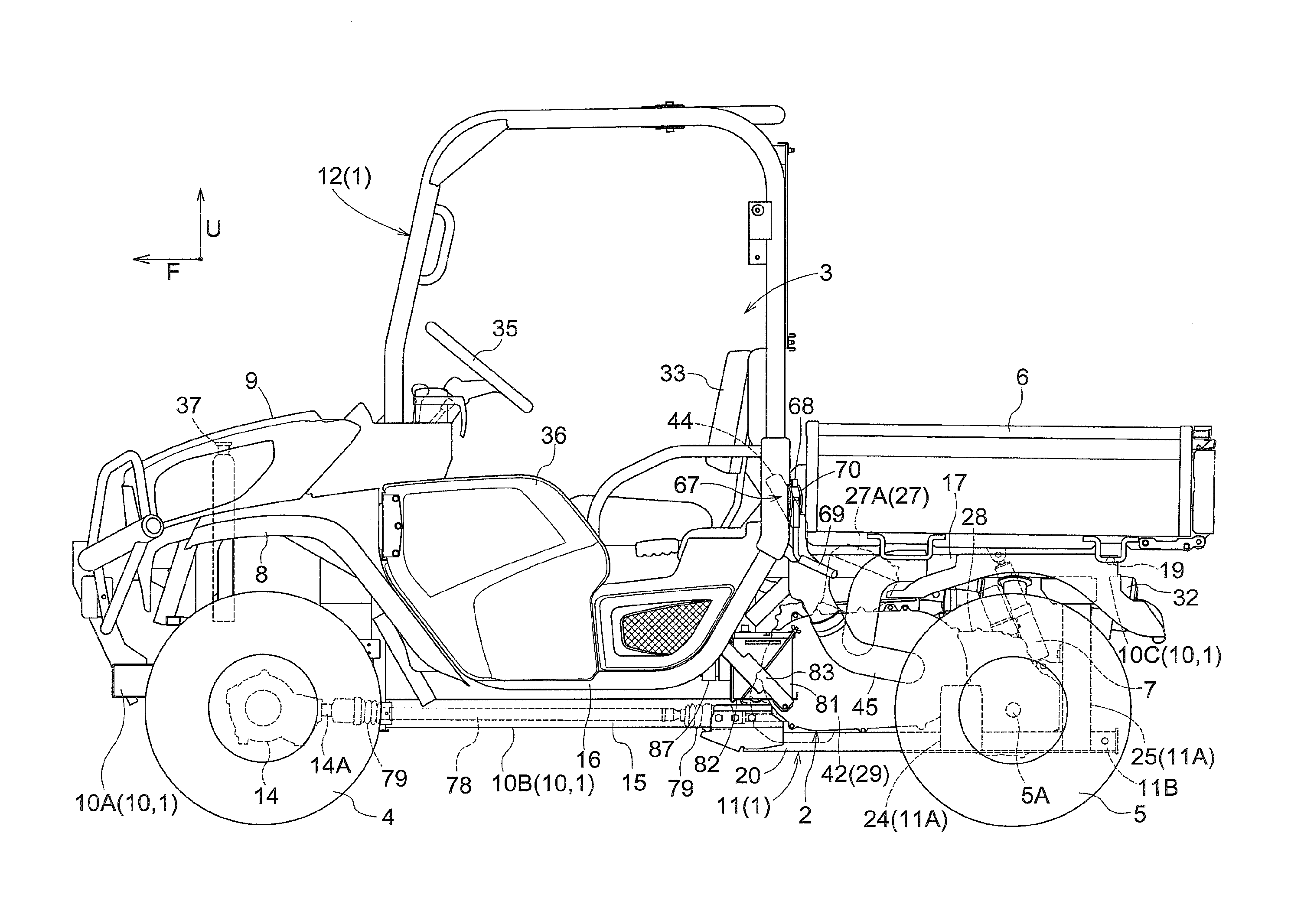
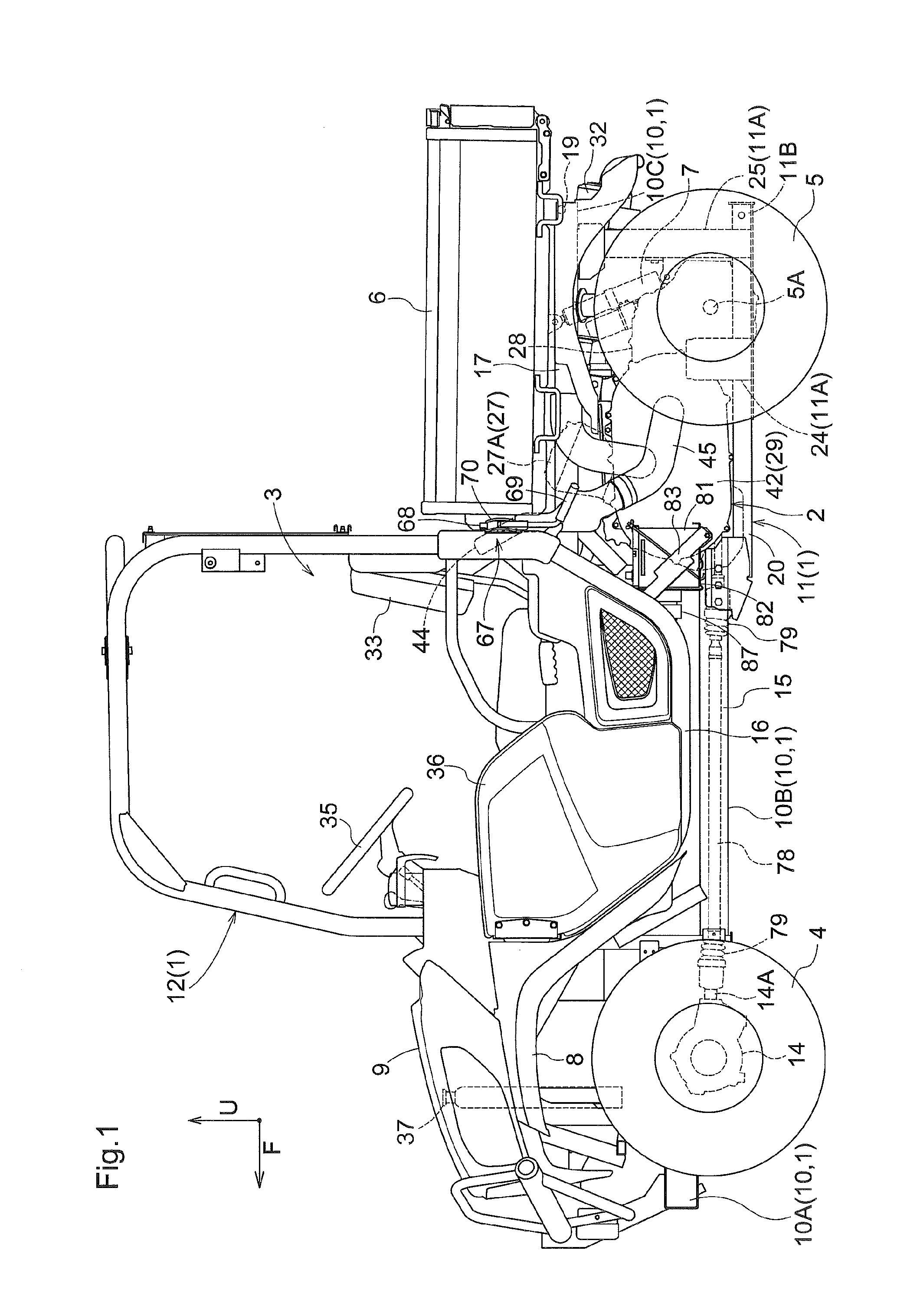
[0115]Next, with reference to FIGS. 1-22, one embodiment of a utility work vehicle according to the present invention will be described.

[0116]In following description, a direction denoted by an arrow of a mark “F” shown in FIG. 1 is the front side of the utility work vehicle directed to the present invention, and a direction denoted by an arrow of a mark “U” is the upper side of the utility work vehicle.

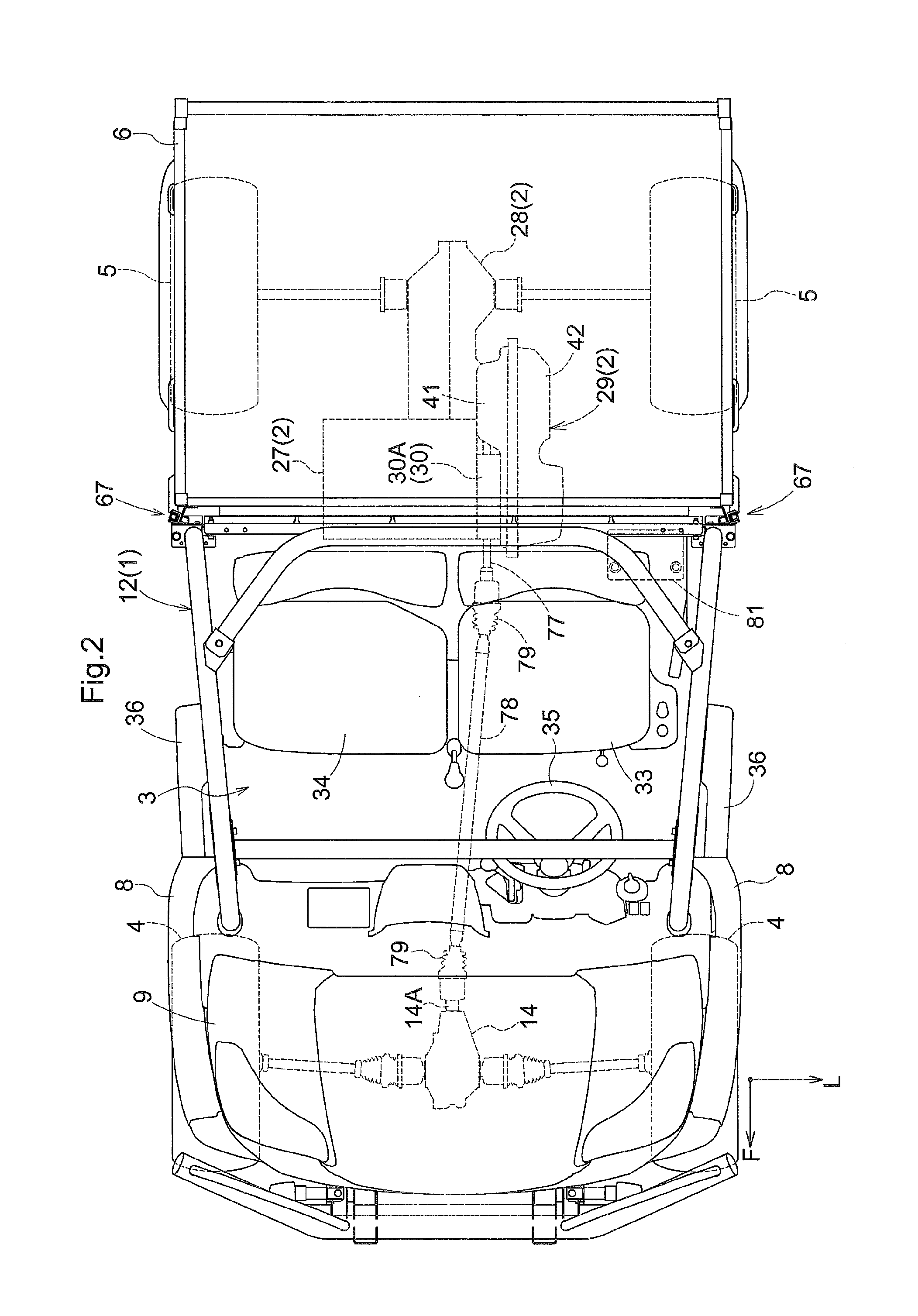
[0117]Also, a direction denoted by an arrow of a mark “F” shown in FIG. 2 is the front side of the utility work vehicle directed to the present invention and a direction denoted by an arrow of a mark “L” is the left side of the utility work vehicle.

[0118]As shown in FIGS. 1-4, the utility work vehicle illustrated in the present embodiment includes: a vehicle body frame 1 forming a framework of the vehicle body; an engine section 2 mounted at a rear portion of the vehicle body; a riding section 3 for two persons mounted at a front / rear intermediate portion of the vehicle body; right a...


PUM


Abstract

Provided is a utility work vehicle including an engine section, a speed changer device and a belt type stepless speed changer device, a rear frame supporting the engine section, and a main frame supporting the rear frame. The rear frame includes right and left rear wheel supporting portions, each of which has a front supporting member and a rear supporting member extending upwards from the rear frame. The rear supporting member disposed on more rear side of the vehicle body than the belt type stepless speed changer device has its upper end connected to a rear frame portion of the main frame. The front supporting member is disposed on more laterally outer side of the vehicle body than the belt type stepless speed changer device. Between an upper end of the front supporting member and the rear frame portion, there is formed a space that allows attachment/detachment of a speed changer cover detachably attached to the belt type stepless speed changer device from a laterally outer side of the vehicle body.

Description

CROSS-REFERENCE TO RELATED APPLICATIONS[0001]This application claims priority to Japanese Patent Application Nos. 2015-133946, 2015-133947, and 2015-133951 all filed Jul. 2, 2015, the disclosures of which are hereby incorporated in their entirety by reference.BACKGROUND OF THE INVENTION[0002]1. Field of the Invention[0003]The present invention relates to a utility work vehicle.[0004]2. Description of Related Art[0005](1) First Related Art[0006]JP 2013-043481 A (U.S. Pat. No. 8,776,939 B2) discloses an example of a utility work vehicle having a rear fame supporting an engine section and a main frame supporting the rear frame. This utility work vehicle includes right and left upper frames and a detachable frame unit supporting a driving section. In this utility work vehicle, the detachable frame unit connects a mount frame to the right and left upper frames via front and rear vertical frames disposed at right and left end portions of the mount frame. Each vertical fame pivotally suppo...

Claims


Application Information

Patent Timeline
IPC IPC(8): B60P1/16B60K1/04B62D21/00B60K13/04B60K13/02
CPCB60P1/16B60K13/04B60K1/04B62D21/00B60K13/02B62D21/11B62D23/005B60K17/08B60K17/344B60K2005/003B60Y2200/20B60Y2400/72B60L53/80Y02T10/70Y02T10/7072
Inventor BESSHO, HIROKIOKABE, KENSUKENAKAMURA, TAROFUJIWARA, JUNICHIONO, TOSHIKIKOMATSU, TAKAFUMI
Owner KUBOTA LTD
Why Eureka
Try Eureka