
Flexible LED light strip for a bicycle and method for making the same

a technology of led light strips and bicycles, applied in cycle equipment, lighting and heating apparatus, light support devices, etc., can solve the problems of less protection against mechanical damage to circuitry, led light strips are typically susceptible to damage, and led light strips are often not desirable for outdoor lighting applications. , to achieve the effect of convenient installation

Active Publication Date: 2013-01-24
LKRB IND LLC
View PDF13 Cites 87 Cited by
  • Summary
  • Abstract
  • Description
  • Claims
  • Application Information

AI Technical Summary

Benefits of technology

This patent is for a flexible LED light system for bicycles that includes two to eight light strips. Each strip has a flexible plastic housing with a flexible electrical cable that connects to an external controller and power source. The light strips can bend over an arc of 20 degrees, and the length of the strips is between 80 mm and 2.0 m. The length to width ratio is at least 8:1. The system can provide a coordinated display on the bicycle when the light strips are mounted.

Problems solved by technology

However, many conventional LED light strips include circuitry housed within hollow tube-like sheathings which provide only minimal protection against mechanical damage to the circuitry due to excessive loads placed on the sheathings.
Also, as the tube-like sheathings are hollow, the LED strips are typically susceptible to damage caused by moisture penetration.
As a result, such LED light strips are often not desirable for outdoor lighting applications or other applications in which the LED strips are exposed to extreme weather conditions or abuse.
However, moisture is often capable of penetrating into the interior of these two-piece EL light strips through the fused or bonded seal joining the two-piece housing, especially when the strips are used in outdoor applications, or after the bonded or fused seal connecting the two-piece housing weakens over time.
In addition, the hard lamination process used to seal the EL lamp configuration is not desirable for LED circuitry, as LEDs are typically greater in height than the substantially flat layers forming the EL lamp configuration.
In addition, the high temperatures required for the bonding or fusing of the strip would subject the LEDs and associated circuitry to heat damage.
Just as with the EL lamps, the two layers of rubber can easily separate from each other or from the flexible circuit under physical stress, or do not effectively seal moisture.
Prior art LED light strips, including those disclosed by the '293 patent, do not effectively address durability, flex and environmental protection of an electrical connection at their end or ends.
In a comparatively small installation such as a bicycle, a rigid electrical connector at the end of the light strip may preclude a clean-looking, form-fitting installation since the electrical connector can't easily match the rest of the light strip in size, shape or flex.
Furthermore, an electrical connector that meets high physical and environmental protection is generally expensive.
The electrical connector is a common failure point in many commercially available light strips.
This may be suitable for an architectural application, but not for a high volume consumer product such as a flexible light strip for bicycles where ease of installation and use is important.

Method used


Image

  • Flexible LED light strip for a bicycle and method for making the same
  • Flexible LED light strip for a bicycle and method for making the same
  • Flexible LED light strip for a bicycle and method for making the same

Examples


Embodiment Construction

[0050]It will be apparent to those skilled in the art, that is, to those who have knowledge or experience in this area of technology, that many uses and design variations are possible for the encapsulated flexible LED light strips disclosed herein. The following detailed discussion of various alternative and preferred embodiments will illustrate the general principles of the invention with reference to specific embodiments suitable for use on a bicycle. Other embodiments suitable for other applications will be apparent to those skilled in the art given the benefit of this disclosure.

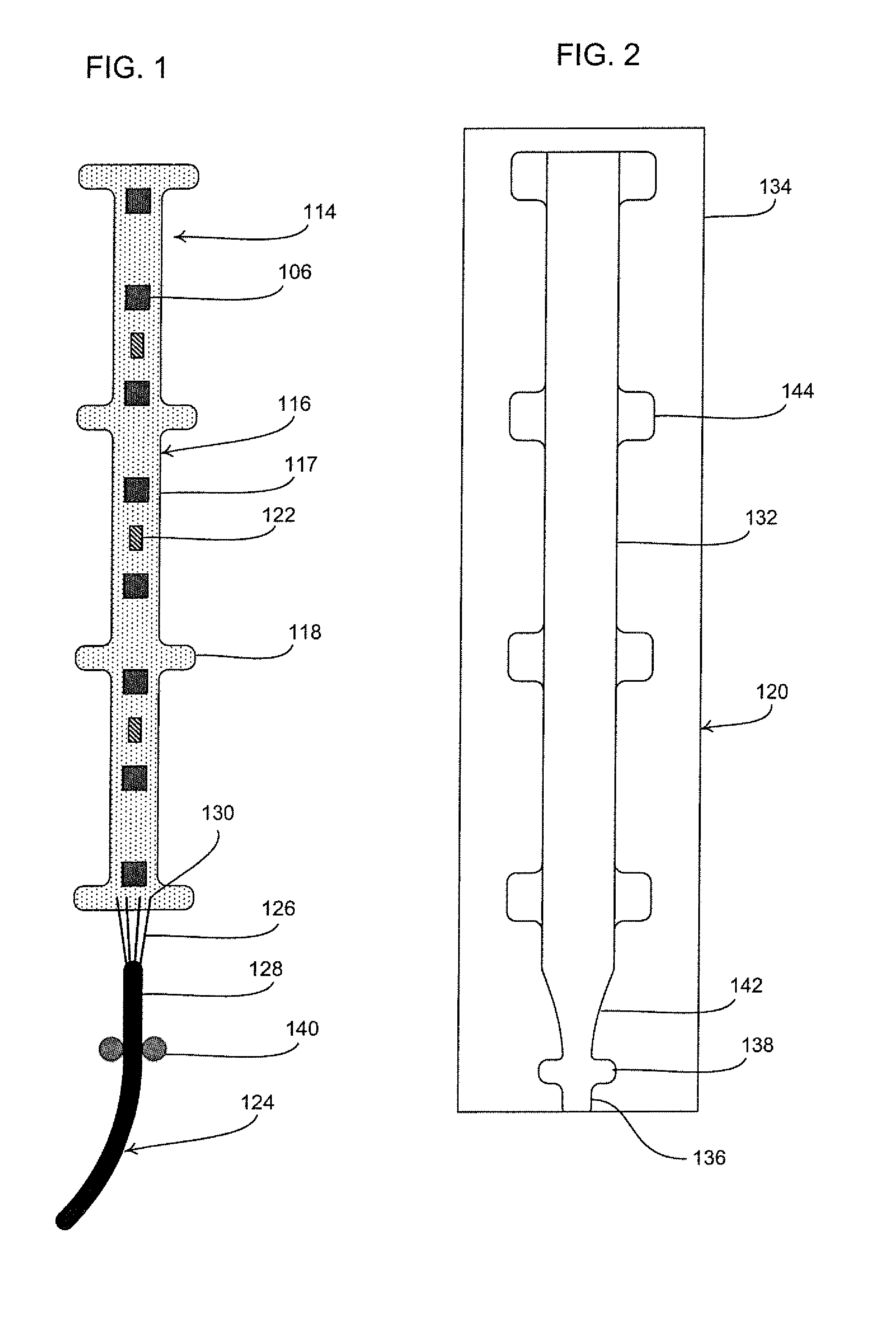
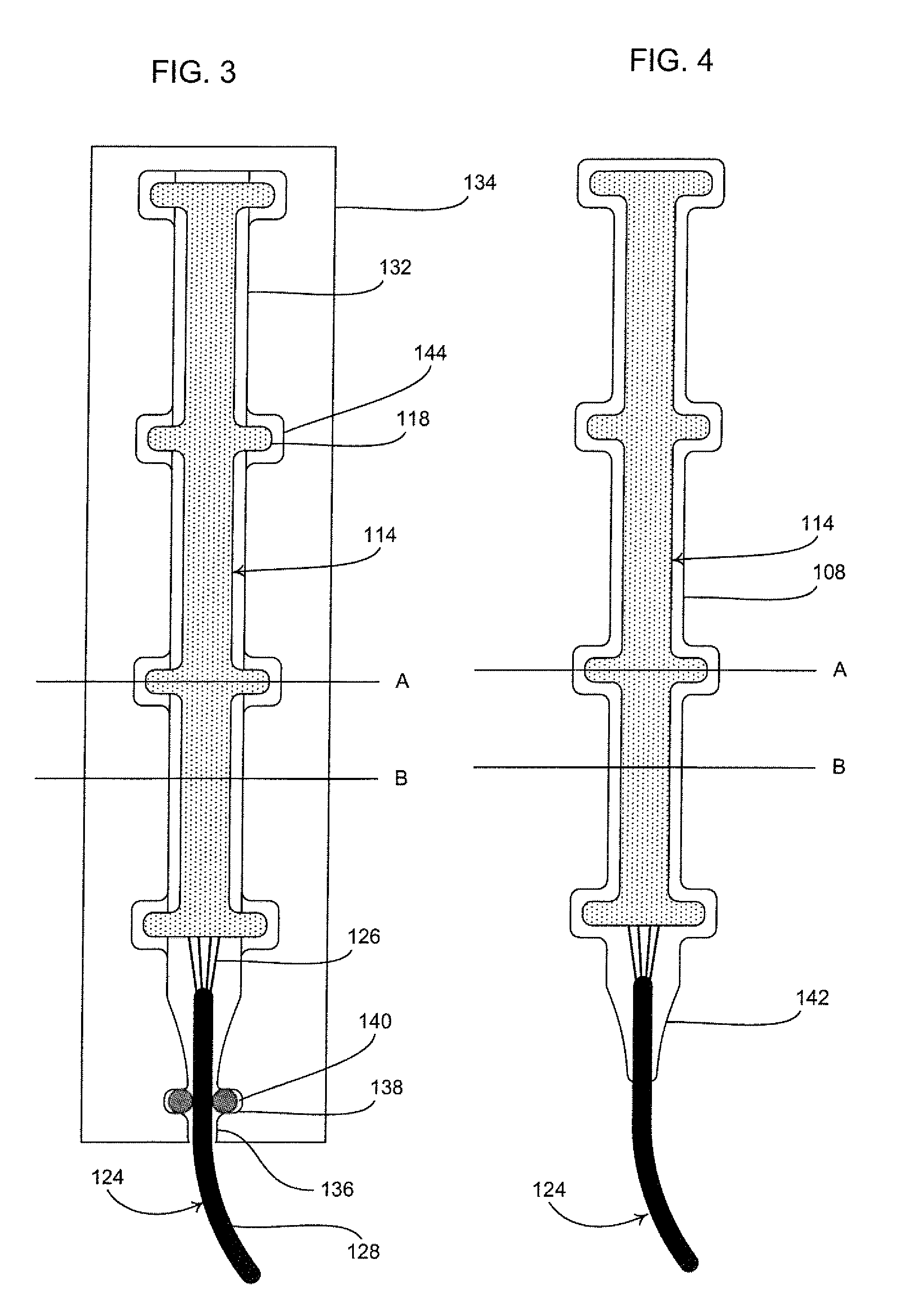
[0051]FIG. 20 illustrates an encapsulated flexible LED light strip 100 according to the present invention. The illustrated encapsulated flexible LED light strip 100 includes a flexible substrate or LED light strip 114 including an LED light circuit 104 having a plurality of LED lights 106 and a clear flexible plastic material fully encapsulating the LED light circuit 104 on all sides to form a seamless s...


PUM

PropertyMeasurementUnit
lengthaaaaaaaaaa
lengthaaaaaaaaaa
lengthaaaaaaaaaa

Abstract

An integrally-formed single-piece flexible light strip includes a substrate populated with at least one LED light circuit. A clear flexible plastic housing is molded around the LED light circuit to completely encapsulate the light circuit. A flexible electrical cable and contoured strain relief for the electrical cable are also integrally formed as part of the light strip to maintain complete environmental and physical protection and eliminate any non-flexible portions of the light strip such as when a connector is used. The light strip is manufactured in a cost efficient manner, and is impervious to moisture penetration and highly resistant to physical damage, thereby allowing the light strip to be used in a variety of applications and environments. The shape of the illustrated light strip is specially designed for attachment to the round tubing of a bicycle frame. The light strip includes an electrical circuit allowing a reduction in the number of wires between the strip and its associated external control and power.

Description

CROSS-REFERENCE TO RELATED APPLICATIONS[0001]Not ApplicableSTATEMENT REGARDING FEDERALLY SPONSORED RESEARCH[0002]Not ApplicablePARTIES TO A JOINT RESEARCH AGREEMENT[0003]Not ApplicableREFERENCE TO APPENDIX[0004]Not ApplicableFIELD OF THE INVENTION[0005]The field of the present invention relates to flexible light strips and, more particularly, specific enhancements in shape and construction of flexible light strips and manufacturing methods for making the same.BACKGROUND OF THE INVENTION[0006]Light emitting diode (LED) light strips can provide markings in dimly lit environments. LED light strips are relatively inexpensive, easy to install, and exhibit long life when compared to similar bulb or lamp based markers. Many varieties of LED light strips and manufacturing methods are well known and widely available.[0007]When using a LED light strip on a bicycle, it is imperative that the LED, and associated circuitry housed within the strip, is protected from damage due to loads and impact...

Claims


Application Information

Patent Timeline
Patent Type & Authority Applications(United States)
IPC IPC(8): B62J6/00B29C45/14F21S4/00
CPCB62J2006/008Y10T156/10F21V27/02F21V31/04F21S4/005F21Y2101/02F21Y2103/003B29L2031/747B29C45/14467B29C45/14639B29C45/14655B60Q1/2696B62J6/20B62K19/40B29C65/5057H01L33/005B62J6/00B62J6/01B62J6/165F21S4/22F21Y2103/10F21Y2115/10
Inventor GOLDWATER, DAN
Owner LKRB IND LLC
Learn More