
Corner rail extrusion

a technology of extrusion and corners, applied in the direction of roofs, superstructure connections, transportation and packaging, etc., can solve the problems of water or other types of leakage or damage, butyl tape does not perform a proper sealing function, and the density of butyl tape, etc., to achieve the effect of facilitating maintaining the dimensional stability of the rail extrusion

Active Publication Date: 2015-10-29
TITAN DISTRIBUTION
View PDF30 Cites 1 Cited by
  • Summary
  • Abstract
  • Description
  • Claims
  • Application Information

AI Technical Summary

Benefits of technology

The invention is a corner rail extrusion that includes a small aluminum insert and a PVC jacket. The extrusion is flexible and can meet the radius of any vehicle wall design without needing pre-bent pieces. The attachment is secure without screws, fasteners, or sealants, as the extrusion maintains its dimensions and can be easily replaced. The extrusion also has good chemical resistance, temperature stability, and can be colored to match decals. Additionally, the extrusion includes a mushroom-shaped cap that allows for easy color matching and replacement.

Problems solved by technology

In the practice of prior art methods of construction, the tolerances in the dimensions of prefabricated panels are typically not sufficiently small so as to permit the assembly of adjacent walls and proper butt joints.
One disadvantage of the use of butyl tape is the density of the tape.
Accordingly, gaps are left which can then lead to water or other types of leakage or damage.
Accordingly, the butyl tape does not perform a proper sealing function at the aforementioned gap and, further, creates a channel through which water can run, thereby infiltrating the joint.
The use of butyl tape is further disadvantageous in that butyl tape typically dries out and chemically breaks down after a period of use.
The butyl tape can then fall out, resulting in further gaps into which water can infiltrate.
Still further, the use of butyl material has another disadvantage, in that it tends to expand when subjected to heat and, further, is subject to migration away from pressure, such that the butyl tape tends (when exposed to hot weather) to creep away from the fasteners and corner rail.
This creeping movement creates gaps which can permit further water infiltration, as well as create cosmetic problems.

Method used


Image

  • Corner rail extrusion
  • Corner rail extrusion
  • Corner rail extrusion

Examples


Embodiment Construction

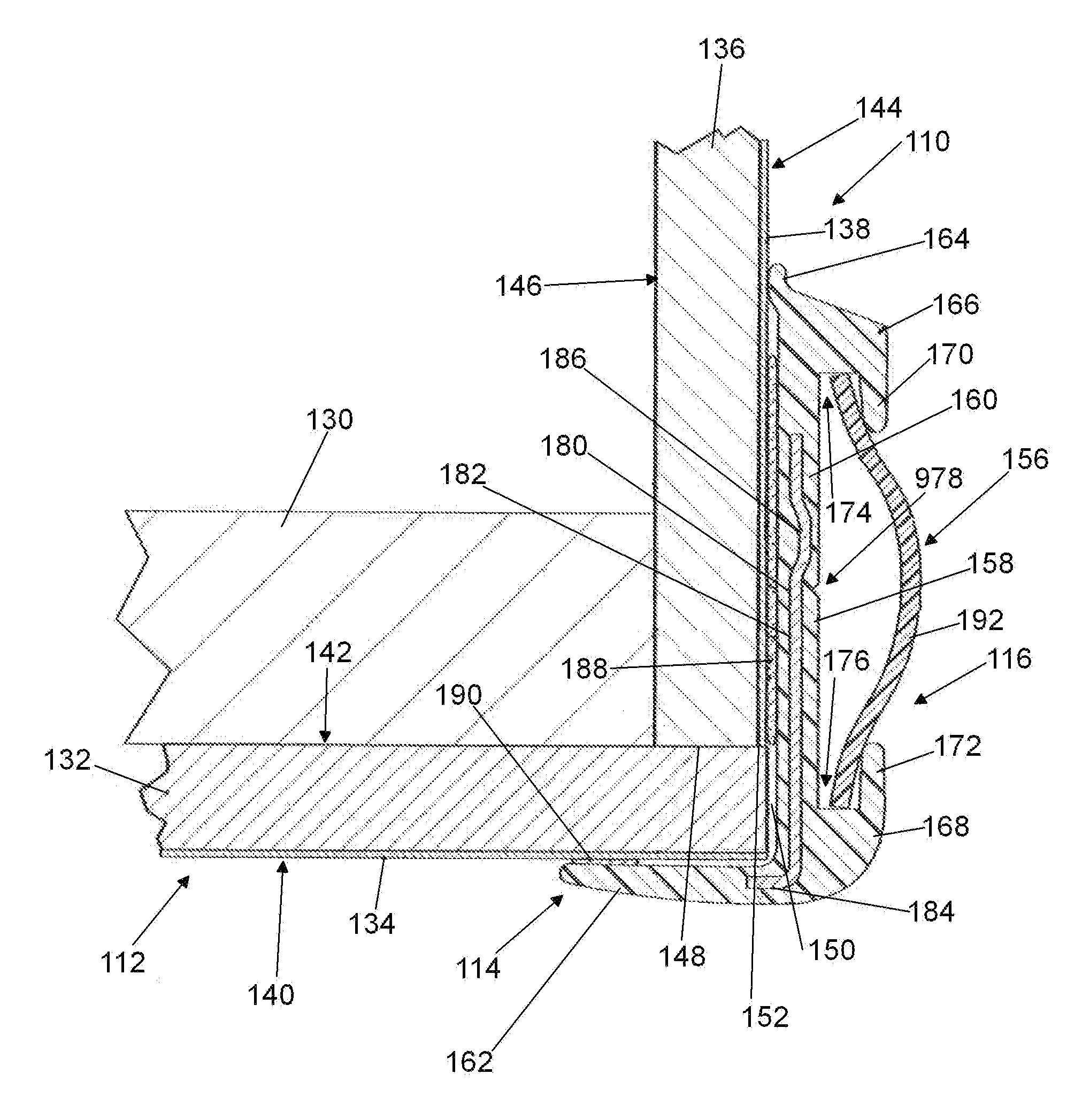
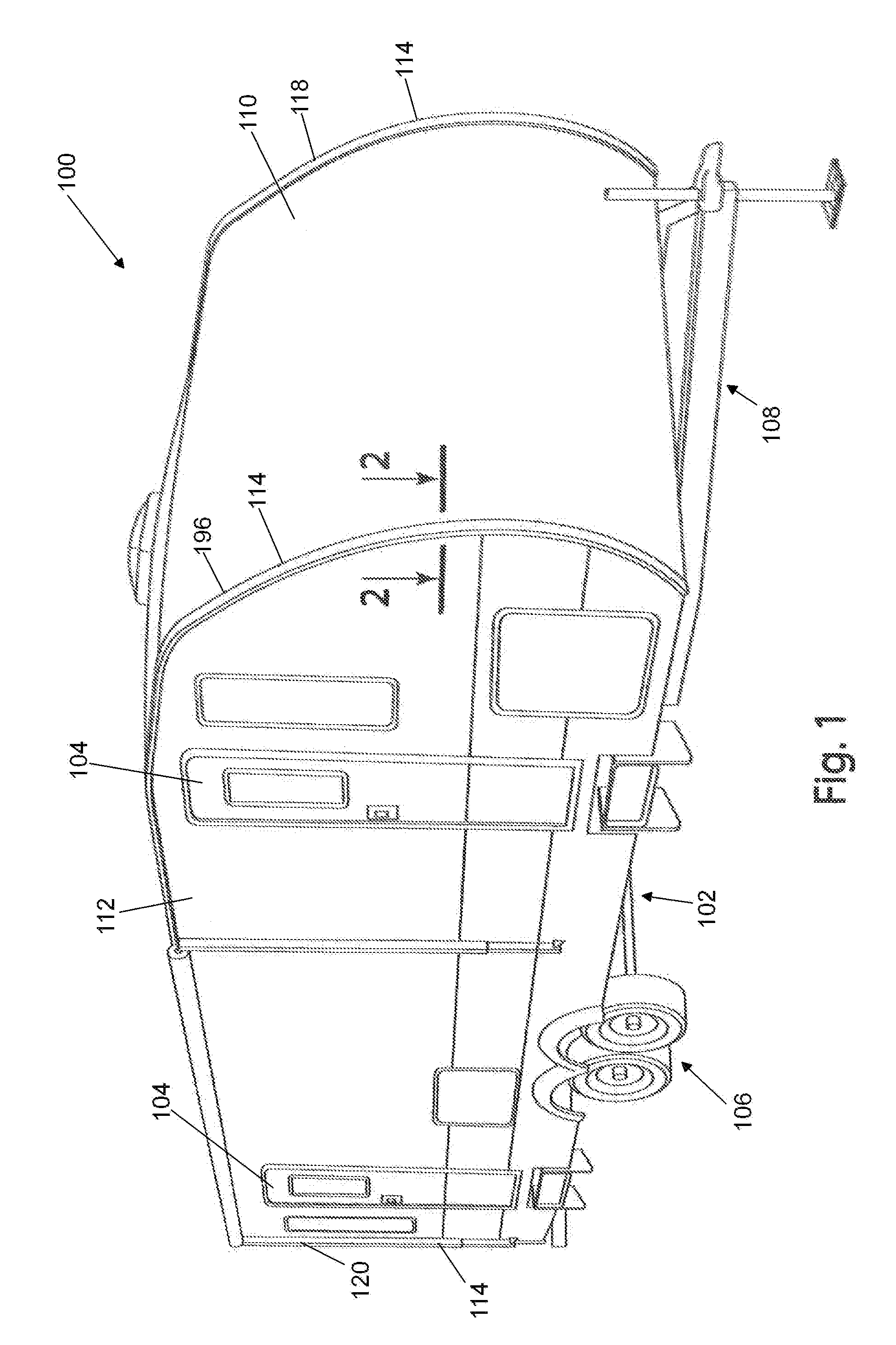
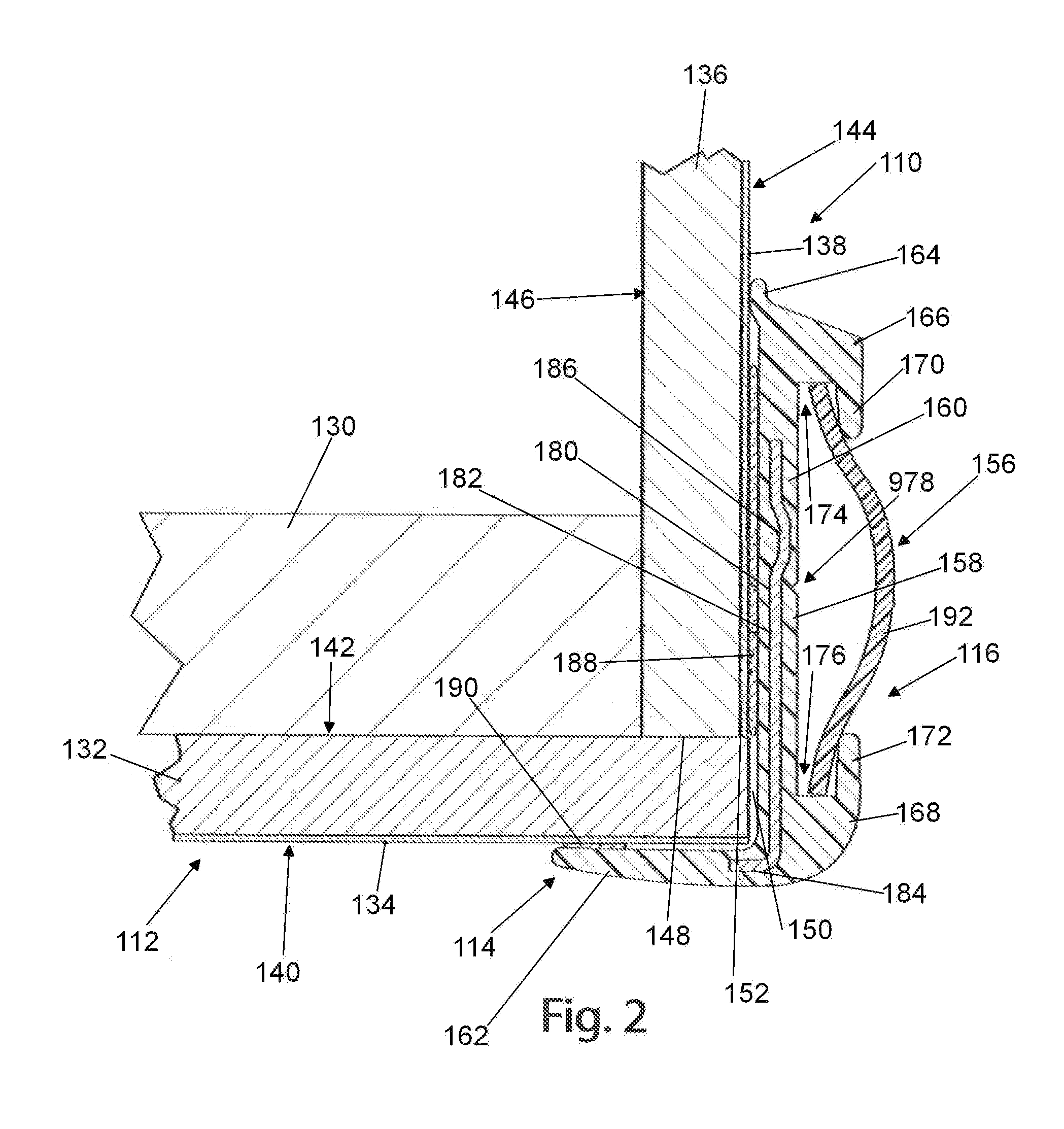
[0037]The principles of the invention are disclosed, by way of example, through the use of corner rail extrusions which may be applied to corner sections of a recreational vehicle, with various elements associated with the invention illustrated in FIGS. 1-5. The disclosure set forth in the following paragraphs and within the drawings describe two embodiments of corner rail extrusions in accordance with the invention. These embodiments are shown specifically with respect to a recreational vehicle as illustrated in FIG. 1. However, it should be understood that the methods and structures disclosed herein in accordance with the invention are applicable to other structures, such as motorized vehicles and buildings (particularly metal buildings).

[0038]Prior to describing the current embodiments of corner rail extrusions in accordance with the invention, a brief description of one embodiment of a corner rail extrusion currently being used in the recreational vehicle industry will be descri...


PUM


Abstract

A corner rail assembly (156) is adapted to be coupled to a corner section (114) of a recreational vehicle (100). The assembly includes a jacket (158) having a main body (160), first leg (162) and second leg (164). A metal insert (180) is formed within an extrusion of said jacket (158). A securing tape (188) in the form of a VHB tape secures the jacket (158) to a front wall (110) of the vehicle (100). A further tape (190) located on an inner side of said first leg (162) affixes the first leg (162) to the side wall (112) of the vehicle (100). A vinyl gimp (192) is releasably coupled to the corner rail assembly (156). A further embodiment of the corner rail assembly (200) includes a mushroom cap insert (216) in place of the vinyl gimp (192).

Description

CROSS-REFERENCE TO RELATED APPLICATIONS[0001]This application claims priority of and is based on U.S. Provisional Patent Application Ser. No. 61 / 985,047 filed Apr. 28, 2014.STATEMENT REGARDING FEDERALLY SPONSORED RESEARCH OR DEVELOPMENT[0002]Not applicable.REFERENCE TO A MICROFICHE APPENDIX[0003]Not applicable.BACKGROUND OF THE INVENTION[0004]1. Field of the Invention[0005]The invention relates to devices for facilitating the sealing of joints at the corners of structures such as recreational vehicles, towable trailers, buildings and similar structures, and, more particularly, to corner rail extrusions for facilitating such joint sealing.[0006]2. Background Art[0007]The general concept of employing means for facilitating sealing of joints in the construction of structures such as towable trailers, motorized recreational vehicles, buildings (particularly metal buildings) and similar structures is known in the prior art. For many of these types of structures, a substantially rigid fra...

Claims


Application Information

Patent Timeline
Patent Type & Authority Applications(United States)
IPC IPC(8): B62D27/02
CPCB62D27/026B62D27/023B60P3/36B60R13/04B62D31/00B62D33/04B62D29/045E04F19/02E04F19/022E04F19/064
Inventor GOODE, TOBIN MICHAEL
Owner TITAN DISTRIBUTION
Learn More