
Conductive film forming method and conductive material

a conductive film and forming method technology, applied in the direction of cable/conductor manufacturing, conductive layers on insulating supports, synthetic resin layered products, etc., can solve the problems of easy activation sites on the surface of polyimide base materials, occurrence of radicals, etc., to achieve superior adhesion to the surface of a base material, high heat resistance, and high endurance

Inactive Publication Date: 2005-12-01
FUJIFILM CORP +1
View PDF18 Cites 7 Cited by
  • Summary
  • Abstract
  • Description
  • Claims
  • Application Information

AI Technical Summary

Benefits of technology

[0011] The invention has been made in consideration of the above problems, and provides a method for forming a conductive film having high heat resistance, superior adhesion to a surface of a base material and high endurance which uses a polyimide base material with low hygroscopicity, low hygroscopic expansion coefficient, and high elasticity in a simple procedure, and further provides a conductive material that has high heat resistance and dimensional stability and is obtained by the method.
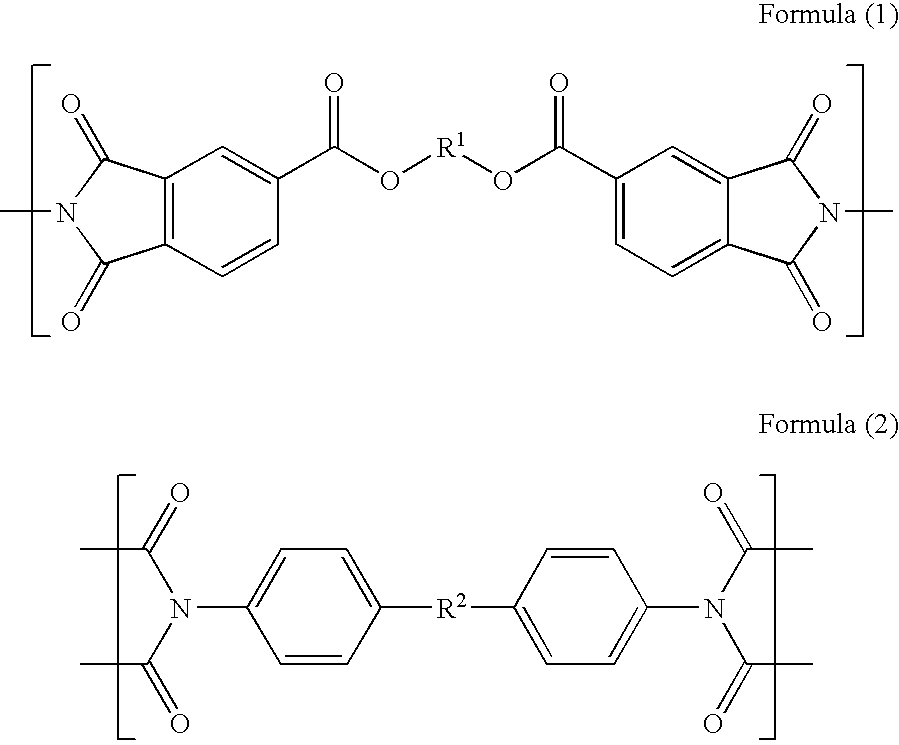
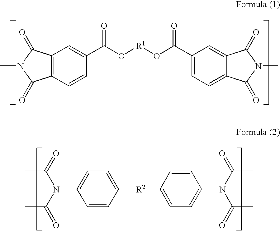
[0012] The inventors of the invention, after investigating the above problems and undertaking diligent research have discovered that the dimensional stability of a conductive film can be maintained by: using a polyimide base material that has low hygroscopicity, low hygroscopic expansion coefficient, and high elasticity; using specific structural units; and, by using the polyimide introduced polymerization initiation sites on the structural skeleton thereof. In addition it has been discovered that when using such a polyimide base material, by applying energy, such as UV light, in the form of a pattern, and by using these activation sites as the starting points, by forming a graft polymer that directly bonds to the surface of the base material and that interacts with either an electroless plating catalyst or a precursor thereof by using the activation site as a starting point, the surface of the polyimide base material can easily be caused to have activation sites (causing the occurrence of radicals).

Problems solved by technology

In addition it has been discovered that when using such a polyimide base material, by applying energy, such as UV light, in the form of a pattern, and by using these activation sites as the starting points, by forming a graft polymer that directly bonds to the surface of the base material and that interacts with either an electroless plating catalyst or a precursor thereof by using the activation site as a starting point, the surface of the polyimide base material can easily be caused to have activation sites (causing the occurrence of radicals).

Method used


Image

  • Conductive film forming method and conductive material
  • Conductive film forming method and conductive material
  • Conductive film forming method and conductive material

Examples


synthesis example 1

Synthesis of Polyimide Precursor 1 (Polyamic Acid 1)

[0142] 4,4′-diaminobenzophenone (28.7 mmol) was dissolved in N-methylpyrrolidone (30 ml) as a siamine compound in the presence of nitrogen and agitated at a room temperature for approximately 30 minutes.

[0143] p-phenylenebis(trimellitic acid monoester acid anhydride) (28.7 mmol) was added to the above solution at 0° C. and agitated for five hours. The reaction fluid was reprecipitated and a polyimide precursor 1 was obtained. The structure thereof was confirmed by means of 1H-NMR and FT-1R.

[0144] Synthesis examples 2 to 8 and Comparative synthesis example 1

[0145] Polyimide precursors 2 to 8 and comparative polyamic acid 1 (polyamic acids 2 to 9), each of which has a composition shown in the following Table 1, were synthesized in a similar manner as in the synthesis example 1.

TABLE 1Tetracarboxylic acid dianhydridecompoundDiamine compoundSynthesis Example 1p-phenylene-bis(trimellitic acid4,4′-diamino benzophenone: 28.7(Polyam...

example 1

Preparation of Surface Graft Polymer

[0147] The polyimide film 1 prepared according to the above-mentioned method was used as a substrate. A coating liquid having the following composition was coated on the substrate using a rod bar #18. A thickness of the film formed on the base material was 0.8 μm. Exposure was then carried out with respect to the obtained film using a 1.5 kW high-pressure mercury-vapor lamp for ten minutes. Thus obtained film was washed with water. Surface graft polymer was introduced on the entire surface of the base material thereby.

Composition of coating liquidPolymer including a polymerizable group0.25g(synthesized in the following method)Cyclohexanone8.0g

Method of Synthesizing Above-Described Polymer Having Polymerizable Group

[0148] 58.6 g of 2-hydroxyethylmetahacrylate was put in a three-neck flask having a 500 ml capacity and 250 ml of acetone was added thereto and then agitated. 39.2 g of pyridine and 0.1 g of p-methoxyphenol were further added there...

example 2

[0152] The metallic film 1 formed in Example 1 was further subjected to electroplating in an electroplating bath containing the following composition for 30 minutes, and thus a conductive film 2 was formed to provide a conductive material 2 of Example 2.

Composition of electroplating bathCopper sulfate38mgSulfuric acid95gChloric acid1mlBrightening agent (trade name KAPPA-GREEM PCM,3mlmanufactured by Meltex Inc.)Water500ml


PUM

PropertyMeasurementUnit
Substance countaaaaaaaaaa

Abstract

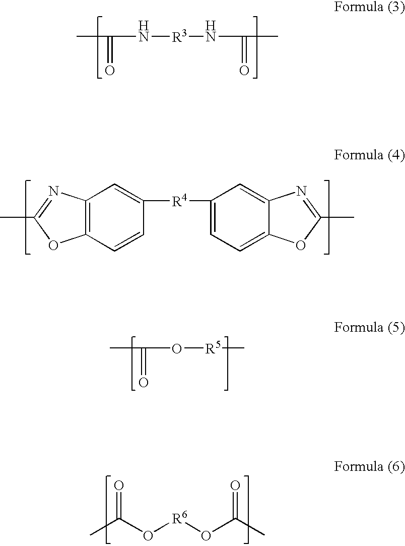
The invention provides a method for forming a conductive film including: applying energy to a surface of a base material including a polyimide having at least one structural unit represented by Formulae (1) or (2) and having a polymerization initiating site in a skeleton thereof to generate an activation site on the surface of the base material; forming a graft polymer that directly bonds to the surface of the base material and that interacts with either an electroless plating catalyst or a precursor thereof by using the activation site as a starting point; applying either an electroless plating catalyst or a precursor thereof to the graft polymer; and electroless plating. R1 represents a bivalent organic group. R2 represents one of Formulae (3) to (6). R3, R4, R1 and R5 independently represent a bivalent organic group.

Description

CROSS-REFERENCE TO RELATED APPLICATION [0001] This application claims priority under 35 USC 119 from Japanese Patent Application No. 2004-163777, the disclosure of which is incorporated by reference herein. BACKGROUND OF THE INVENTION [0002] 1. Field of Invention [0003] This invention relates to a conductive film forming method and a conductive material, and in detail, specifically relates to a conductive film forming method that provides conductive films which are superior in adhesion property, wearing resistance and dimensional stability on polyimide base materials having small moisture absorption ratio and hygroscopic expansion coefficient in a simple processes, and further relates to a conductive material that is obtainable by the method. [0004] 2. Description of the Related Art [0005] Polyimide is a polymer which has extremely high stability against heat, thus it is used in various materials which are required for heat resistance. Specifically, for the purpose of utilization in...

Claims


Application Information

Patent Timeline
IPC IPC(8): B32B15/00C08F2/46C08G73/10C08G73/14C08G73/16C08G73/22C23C18/20H01B5/14H01B13/00H05K1/03H05K3/38
CPCC08G73/10C08G73/14C08G73/16C08G73/22C23C18/206H05K1/0346H05K3/387H05K2201/0154C23C18/30C23C18/20Y10T428/31721
Inventor KANO, TAKEYOSHIKAWAMURA, KOICHI
Owner FUJIFILM CORP
Learn More