Valve box, valve control device and assembly thereof

a control device and valve box technology, applied in the field of valve boxes, can solve the problems of lateral force applied to the valve box, time-consuming and tiresome, and the possibility of different kinds of trades moving about the lots, and achieve the effects of enhancing its rigidity, long-term rigidity and strength, and maintaining the stability of the circumferential dimension

Active Publication Date: 2012-01-10
THE WATER BOX DEV CORP
View PDF10 Cites 7 Cited by
  • Summary
  • Abstract
  • Description
  • Claims
  • Application Information

AI Technical Summary

Benefits of technology

[0014]In a further variant, a hollow plug, which is like a stent, preferably comprised of a stiff material, and more preferably, a carbon-fiber, is inserted into the tubing at a bend or deformable location for long term rigidity and strength.
[0015]In yet a further variant, a portion of the tubing which is sub-grade is thickened or otherwise reinforced with tougher, relatively more rigid compounds to strengthen the tubing and enhance its rigidity.
[0016]In still another variant, to maintain circumferential dimension stability and to minimize distortion or distension of the tubing, a high density foam material in a generally cylindrical shape is installed temporarily into the tubing. Because the foam material is to be removed from the tubing, a mechanical fastener or a rope, et al., is attached to the foam material to be used to assist in withdrawing the material from the tubing. The foam material is bendable, yet is dense enough to prevent lateral kinking and distortion of the tubing due, for example, from external force applied to the tubing, for example, caused by heaving machinery passing over the ground adjacent to the valve box.
[0018]Preferably, the support member further includes a base having a first portion and a second portion, each of the portions has a side wall and a bottom wall forming a “L” shape, the first and second portions are respectively attached to the lower end of the tubular section and disposed in juxtaposition relative to each other so as to form a tunnel, to enable passage therethrough of a pipeline on which a valve underneath the valve box is located. Therefore, even when run over by a very heavy machinery, the base of the support member may substantially disperse the loads and pressures from above, avoiding the sometimes inevitable result that the pipeline is pushed down by an edge of the lowest end of the valve box.
[0019]Preferably, the resilient tubular member may further have a mark in alignment with the orientation of the pipeline, on its outside wall, so as to indicate the location of the pipeline conveniently.

Problems solved by technology

But, even this arrangement requires a special wrench or key to turn the valve on or off.
However, during subsequent construction activities, there are chances that different kinds of trades will move about the lots.
It is not uncommon for heavy machinery to damage the installed valve boxes by running them over or inadvertently burying them, resulting in costly repairs or replacements or requiring searching for and excavating buried valve boxes, which is both time-consuming and tiresome.
Further, there may be lateral force applied to the valve box due to displaced water saturated soil, rocks and / or roots.
There also exists another problem in controlling the underground valve.
In many cases, it perhaps leans toward a side, consequently making it very difficult to reach and locate the top end of the control rod from above the ground level.
Usually, it takes a long time to fish out the control rod, by making many attempts.
There is still another problem in the prior art when the valve boxes are run over by unexpected huge or heavy machinery.
Once this happens, it will be very difficult for it to be discovered and repaired.
However, neither of these patents addresses the above-mentioned problems.

Method used


Image

  • Valve box, valve control device and assembly thereof
  • Valve box, valve control device and assembly thereof
  • Valve box, valve control device and assembly thereof

Examples


Embodiment Construction

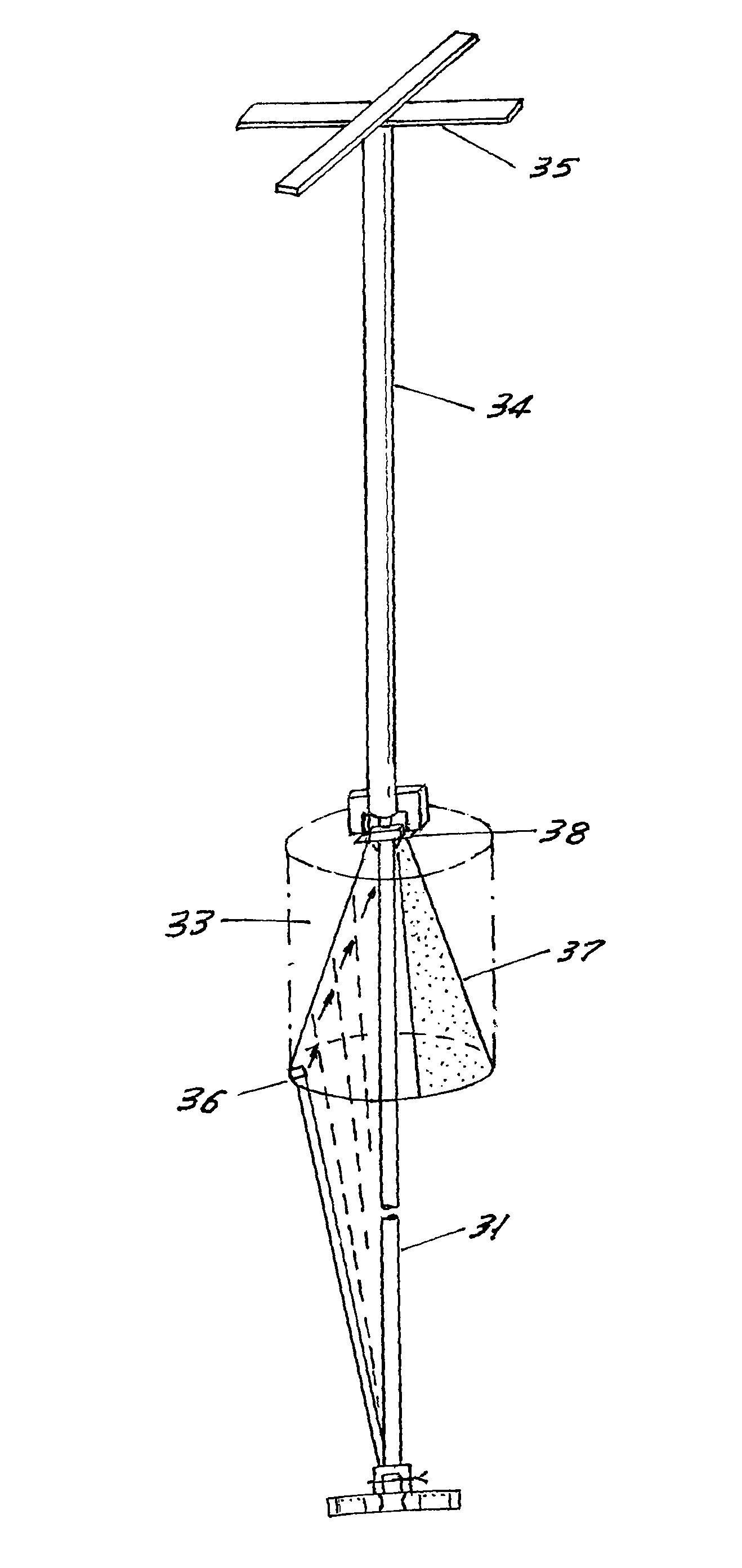
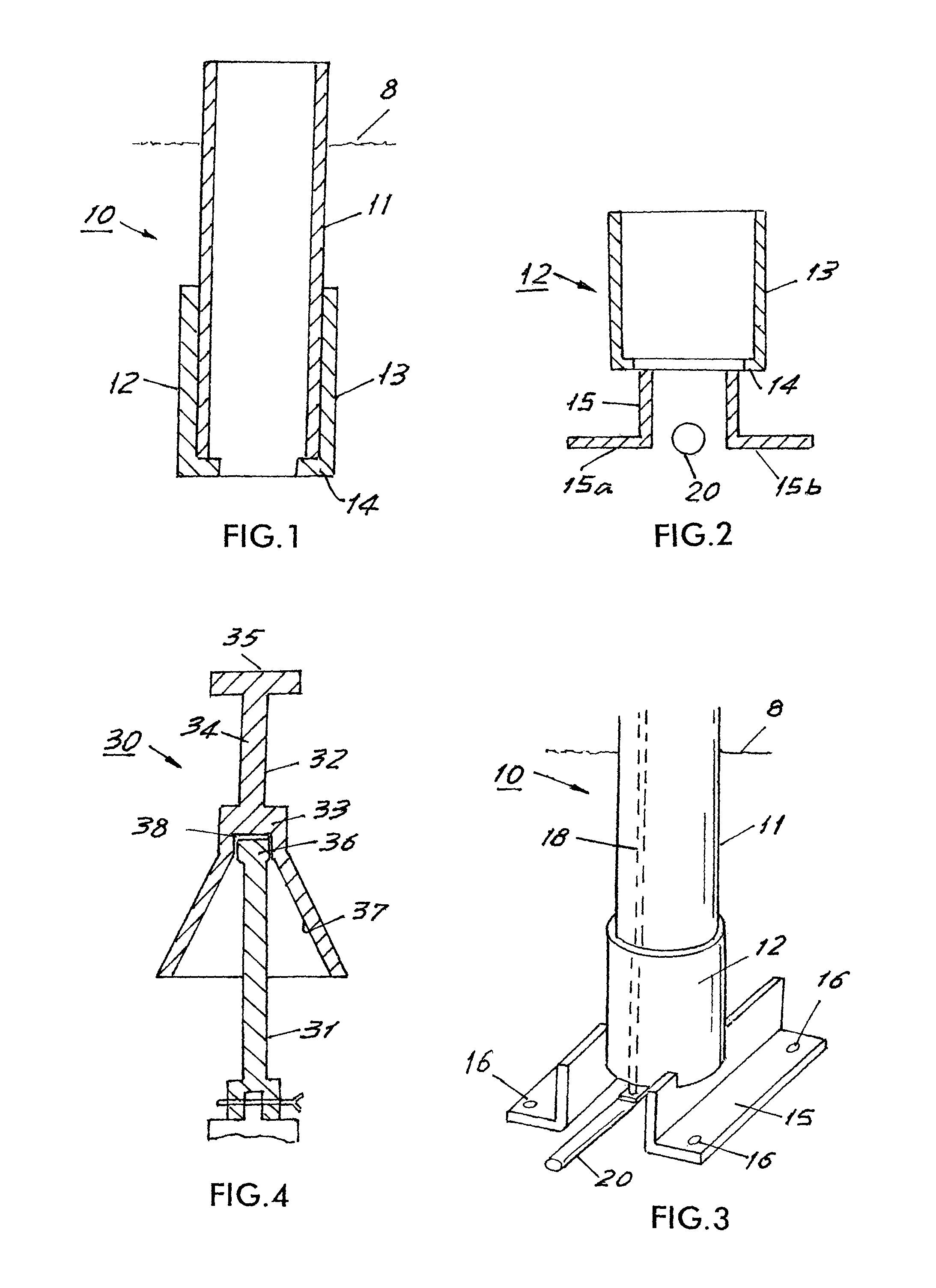
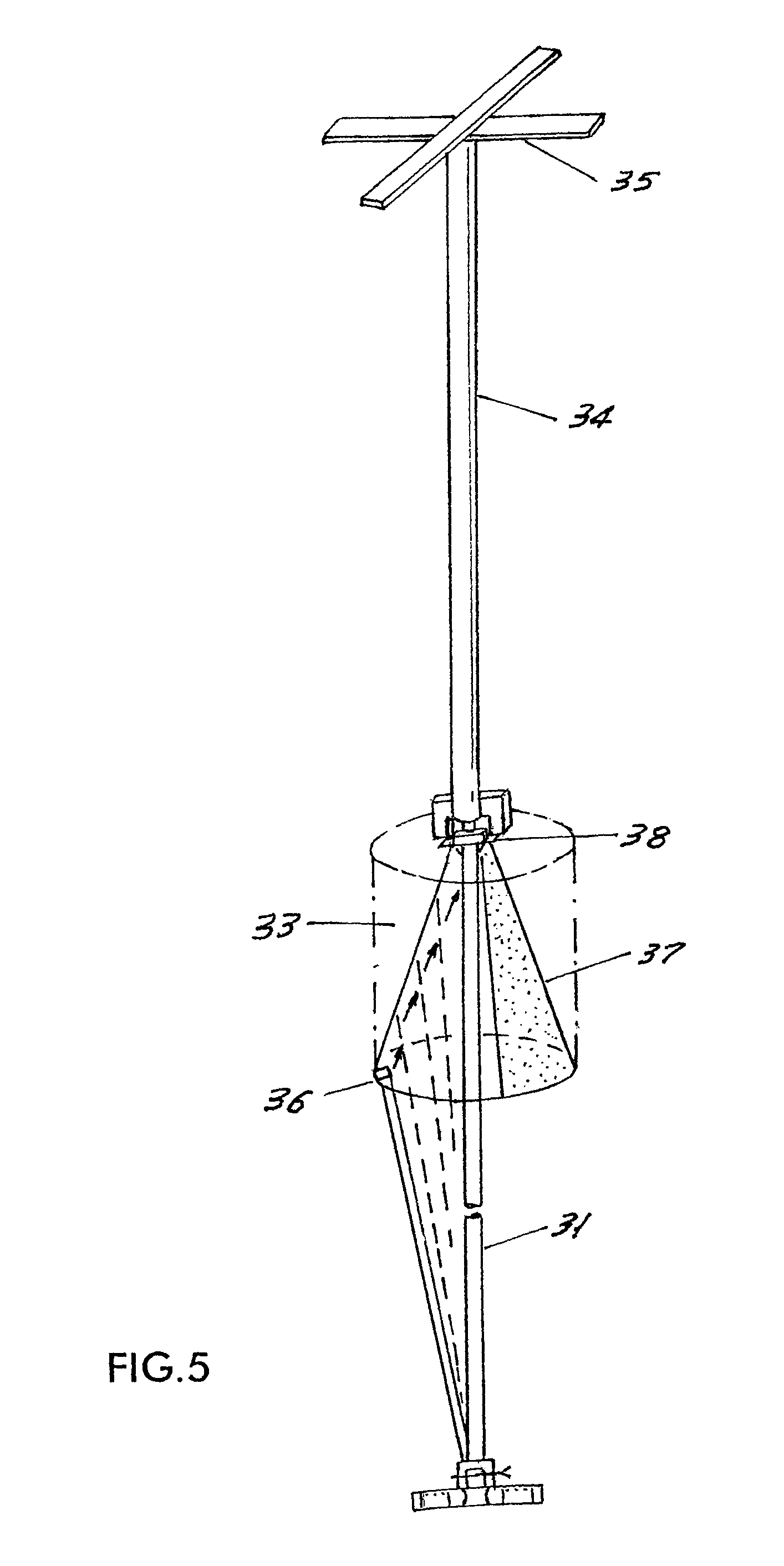
[0039]In the following detailed description, preferred embodiments of the present invention will be described. While a valve box is referred to throughout the preferred embodiments and drawings, it should be noted that a valve box is just an example of a valve can, that is, an access conduit between an underground valve and the upper end to access the valve from aboveground. The present invention can be incorporated in many valve can embodiments, and the present invention is not limited to any particular valve can described. The valve upon which the valve can is positioned may comprise any type of valves suitable for aboveground access, such as gas valves, water valves, and other flow-control devices. The invention is not limited to valve cans per se, but can also be used in other applications wherein above ground access is required to below ground devices. Such devices include, but are not limited to, electrical switches, reset breakers, and so on.

[0040]Referring now to FIG. 1, the...


PUM


Abstract

A valve box, a valve control device, an assembly thereof and a method are provided for accessing an underground valve and indicating presence and position of the underground valve. The valve box includes a support member having a tubular section; and a resilient tubular member telescopable slidably into the tubular section of the support member. An upper end of the resilient tubular member is extendable above the ground. Various elements are disclosed for stiffening the tubular member against deformation due to forces applied to it. The valve control device comprises a control rod having one end attachable to the underground valve and a control key including a key head, a key handle and a key stem. The key head has a cone-shaped cavity and a recess portion at the top of the cavity, the recess portion being dimensioned to engage a projection at the other end of the control rod.

Description

CROSS-REFERENCE TO RELATED APPLICATION[0001]This is a continuation-in-part application of U.S. patent application Ser. No. 11 / 492,555, filed Jul. 25, 2006, by Edward Weisz, et. al. entitled VALVE BOX, VALVE CONTROL DEVICE AND ASSEMBLY THEREOF.FIELD OF THE INVENTION[0002]The present invention generally relates to valve boxes and associated valve control devices for accessing an underground valve from an above ground position, in particular, to a valve box, a valve control device and the assembly thereof which provide easy access to the underground valve and clear indication of the presence and position of the valve during all phases of constructions and use. The valve box may also be referred to as a water box. A water box of the invention may also remain in place after construction has been completed.BACKGROUND OF THE INVENTION[0003]There are many pipes such as gas pipelines, water and sewer mains typically laid and buried underground, so that municipal utility companies may supply ...

Claims


Application Information

Patent Timeline
Patent Type & Authority Patents(United States)
IPC IPC(8): F16L5/00
CPCB25B13/48E03B9/08F16K27/006F16K31/46Y10T137/7021Y10T137/701Y10T137/7014Y10T137/6999Y10T137/0318Y10T137/7017
Inventor WEISZ, EDWARDWHITESIDE, JON
Owner THE WATER BOX DEV CORP
Why Eureka
Try Eureka