Decoupling element for a fuel-injection device

a fuel injection device and decoupling element technology, applied in the direction of liquid fuel feeders, machines/engines, electric control, etc., can solve the problems of high cost, difficult assembly, resource-intensive noise damping types, etc., and achieve low rigidity of decoupling elements, simple design, and good noise damping

Active Publication Date: 2020-05-05
ROBERT BOSCH GMBH
View PDF25 Cites 0 Cited by
  • Summary
  • Abstract
  • Description
  • Claims
  • Application Information

AI Technical Summary

Benefits of technology

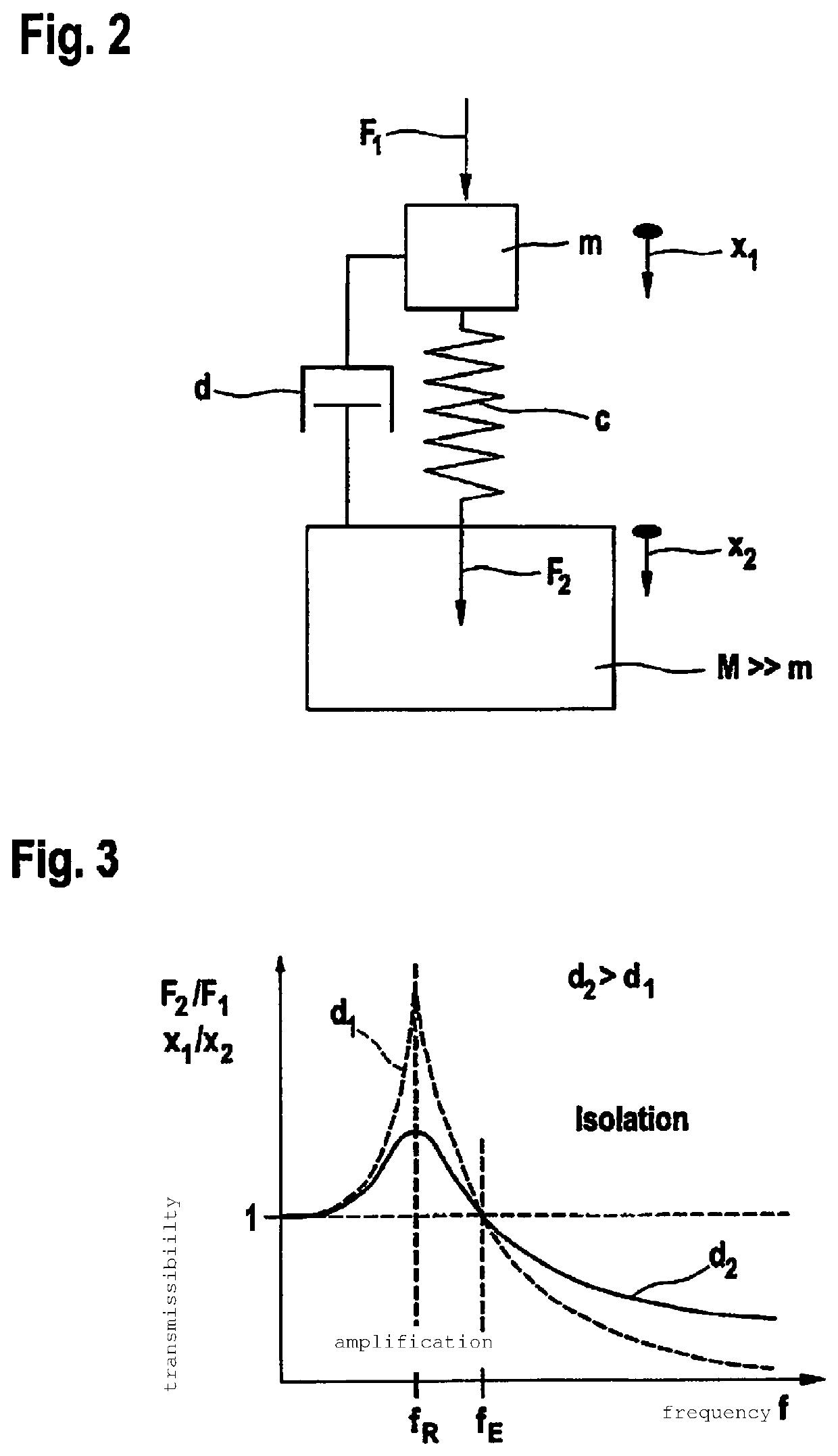
[0007]An example decoupling element in accordance with the present invention may have the advantage that better noise damping is achieved with the aid of a very simple design. The decoupling element has a non-linear, progressive spring characteristic that results in multiple positive and advantageous aspects during the installation of the decoupling element in a fuel-injection device including injectors for a direct injection of fuel. The low rigidity of the decoupling element in the idling operating point allows for effective decoupling of the fuel injector from the cylinder head and thereby markedly reduces the noise radiated by the cylinder head in the noise-critical idling operation. The high rigidity at a nominal system pressure ensures an overall low movement of the fuel injector during the vehicle operation and thereby ensures not only the durability of the sealing rings serving as combustion-chamber seal and as seals from the fuel rail but also a stable spray-discharge point of the fuel spray in the combustion chamber, which is decisive for the stability of some combustion methods.
[0008]The decoupling element is distinguished by low height, which allows for its use also when space is limited. The decoupling element furthermore has long-term strength even at high temperatures. The decoupling element is able to be produced in a very simple and cost-effective manner from the standpoint of production technology. The entire suspension of the system made up of fuel injector and decoupling element may furthermore be installed and uninstalled in a simple and rapid manner.

Problems solved by technology

However, this type of noise damping is very resource-intensive, difficult to assemble and costly.

Method used


Image

  • Decoupling element for a fuel-injection device
  • Decoupling element for a fuel-injection device
  • Decoupling element for a fuel-injection device

Examples


Embodiment Construction

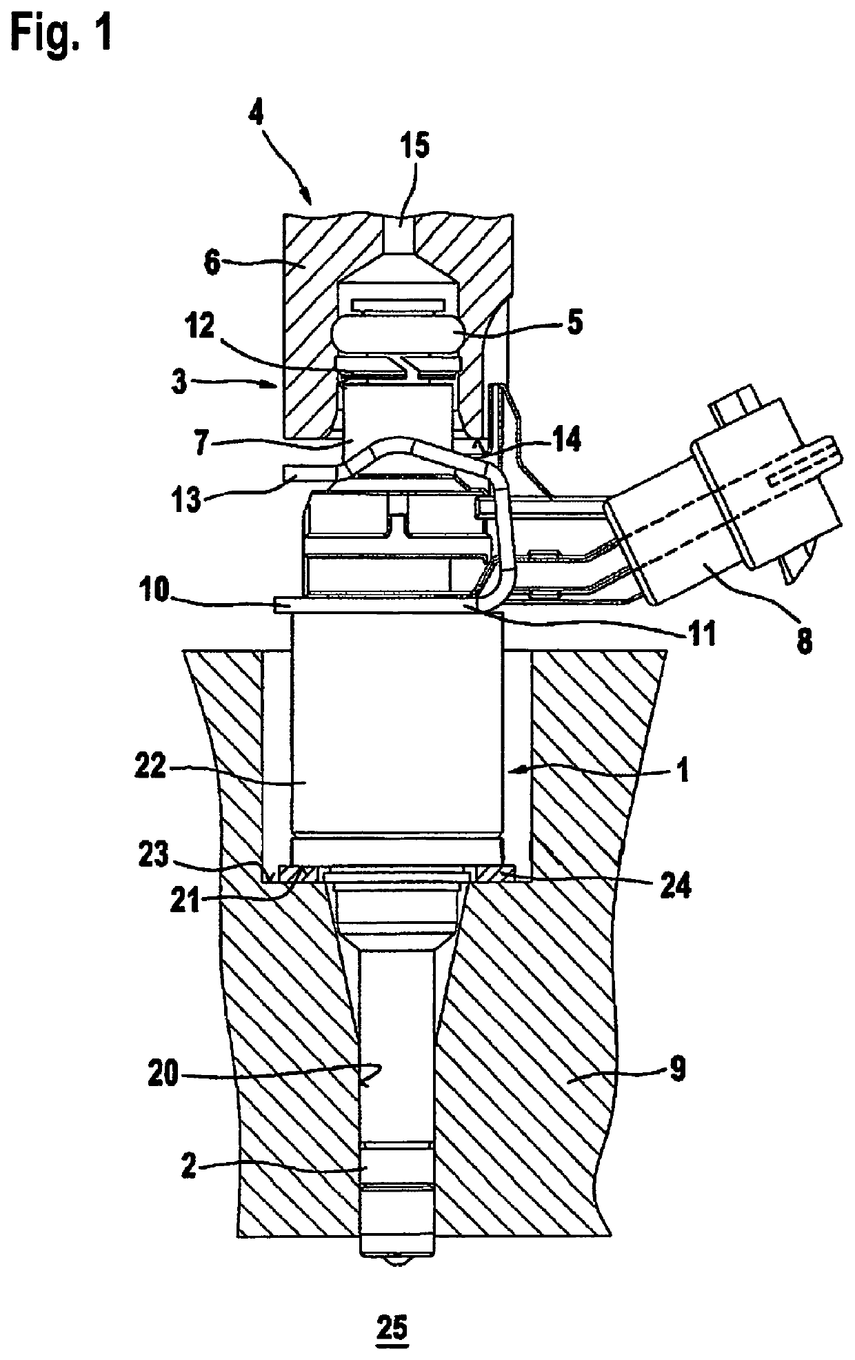
[0019]For an understanding of the present invention, a conventional specific embodiment of a fuel-injection device is described in greater detail below on the basis of FIG. 1. FIG. 1 shows a valve in the form of an injector 1 for fuel-injection systems of mixture-compressing internal combustion engines having externally supplied ignition, as an exemplary embodiment in a side view. Fuel injector 1 is part of the fuel-injection device. Via a downstream end, fuel injector 1, which is implemented in the form of a directly injecting injector for the direct injection of fuel into a combustion chamber 25 of the internal combustion engine, is installed in a receiving bore 20 of a cylinder head 9. A sealing ring 2, in particular made from Teflon®, provides optimum sealing of fuel injector 1 from the wall of receiving bore 20 of cylinder head 9.

[0020]A flat intermediate element 24, which is implemented as a bracing element in the form of a washer, is inserted between a step 21 of a valve hous...


PUM


Abstract

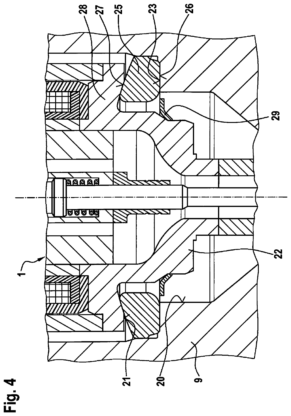
A decoupling element for a fuel-injection device has a low-noise and pivotable construction. The fuel-injection device includes at least a fuel injector and a receiving bore in a cylinder head for the fuel injector as well as the decoupling element between a valve housing of the fuel injector and a wall of the receiving bore. The decoupling element is in the form of a ring, in particular a closed ring, which has a lower end face that sits on a shoulder of the receiving bore, and which has an upper end face that rises conically from radially outside toward radially inside and is in intimate contact with a spherically curved shoulder area of the valve housing of the fuel injector. The fuel-injection device is particularly suitable for the direct injection of fuel into a combustion chamber of a mixture-compressing combustion engine having externally supplied ignition.

Description

FIELD[0001]The present invention is based on a decoupling element for a fuel-injection device.BACKGROUND INFORMATION[0002]FIG. 1 shows a conventional fuel-injection device by way of example. Here, a flat intermediate element is provided on a fuel injection valve installed in a receiving bore of a cylinder head of an internal combustion engine. In the conventional manner, such intermediate elements are positioned as support elements in the form of a washer on a shoulder of the receiving bore of the cylinder head. Intermediate elements of this kind are meant to compensate for production and installation tolerances and to ensure that transverse forces will not affect the mounting even if the fuel injector is positioned at a slight tilt. The fuel-injection device is especially suitable for use in fuel-injection systems of mixture-compressing internal combustion engines having externally supplied ignition.[0003]Another type of simple intermediate element for a fuel-injection device is de...

Claims


Application Information

Patent Timeline
Patent Type & Authority Patents(United States)
IPC IPC(8): F02M63/02F02M55/04F02D41/38F02M61/14F02M61/16F02M69/38F02M55/00
CPCF02M61/168F02M61/166F02M55/04F02M63/026F02D41/3845F02M61/14F02M69/38F02M2200/09F02M2200/50F02M55/004
Inventor SCHEFFEL, MARTINREINHARDT, WILHELM
Owner ROBERT BOSCH GMBH
Why Eureka
Try Eureka