Fuel injection valve

a fuel injection valve and valve needle technology, applied in the direction of valve details, spray nozzles, electromagnets, etc., can solve the problems of inability to precisely vary the stroke of the valve needle, the number of strokes per work cycle of the internal combustion engine is very limited, and the effect of affecting the operation of the valv

Inactive Publication Date: 2011-10-04
COMPACT DYNAMICS
View PDF21 Cites 1 Cited by
  • Summary
  • Abstract
  • Description
  • Claims
  • Application Information

AI Technical Summary

Benefits of technology

[0010]In the case of known fuel injection valves, therefore, there is the problem of providing a compactly constructed, inexpensive arrangement of a fuel injection valve which has long-term strength and is suitable for use in large production lots, and is capable of executing, with the necessary opening / closing forces, a sufficiently high number of strokes per work cycle of the internal combustion engine. The aim of the present invention is to provide fuel injection valves which can contribute towards reducing the fuel consumption of internal combustion engines, in order thereby to increase the thermodynamic efficiency of the internal combustion engine.Solution According to the Invention
[0043]Furthermore, according to the invention, the solenoid arrangements are embedded in or bonded to the partial yokes. This increases the long-term operating strength of the fuel injection valve arrangement.

Problems solved by technology

Inherent in these known arrangements, however, is the disadvantage that the number of strokes per work cycle of the internal combustion engine is very limited.
In particular, with these arrangements it is not possible, in the case of high-speed internal combustion engines, to provide the required number of multiple injections per work cycle that are necessary for efficient engine management.
In addition, in the case of these arrangements the precise variation of the stroke of the valve needle is possible only to a very limited extent.
In both respects, the conventional electromagnetic actuating devices have been found to be a limiting factor for the further development of efficient fuel injection valves.
A known approach for overcoming this limitation consists in the provision of a piezo-linear actuator instead of the electromagnetic actuating device, Apart from the high costs and the relatively large structural space required by the piezo-linear actuator, its temperature-dependent behaviour, in immediate proximity to the combustion chamber of an internal combustion engine, is also disadvantageous.
Overall, a relatively large-scale use of this type of fuel injection valve in production vehicles has been rejected hitherto.
In addition, the stroke travel of a piezo-linear actuator is very limited for a given overall length, and is currently increased to approximately 100 to 200 μm by means of complex lever arrangements.
Finally, the precise modulation of the stroke of the jet needle by means of the piezo-linear actuator continues to prove difficult in the case of the high dynamic response and the increasingly high pressures in the combustion chamber, particularly in the case of diesel direct injection.
However, the structural and electrical / magnetic symmetry of the solenoid system that is necessary in the case of this arrangement, for example the dimensioning or the ratio of the radial sectional areas of the pole bodies relative to one another, constitutes a substantial limitation.
Moreover, in the case of this known arrangement, likewise, the valve switching times, valve travels and valve closing forces that can be achieved must be described as unsatisfactory, at best, in view of the requirements explained at the beginning.

Method used


Image

  • Fuel injection valve
  • Fuel injection valve
  • Fuel injection valve

Examples


Embodiment Construction

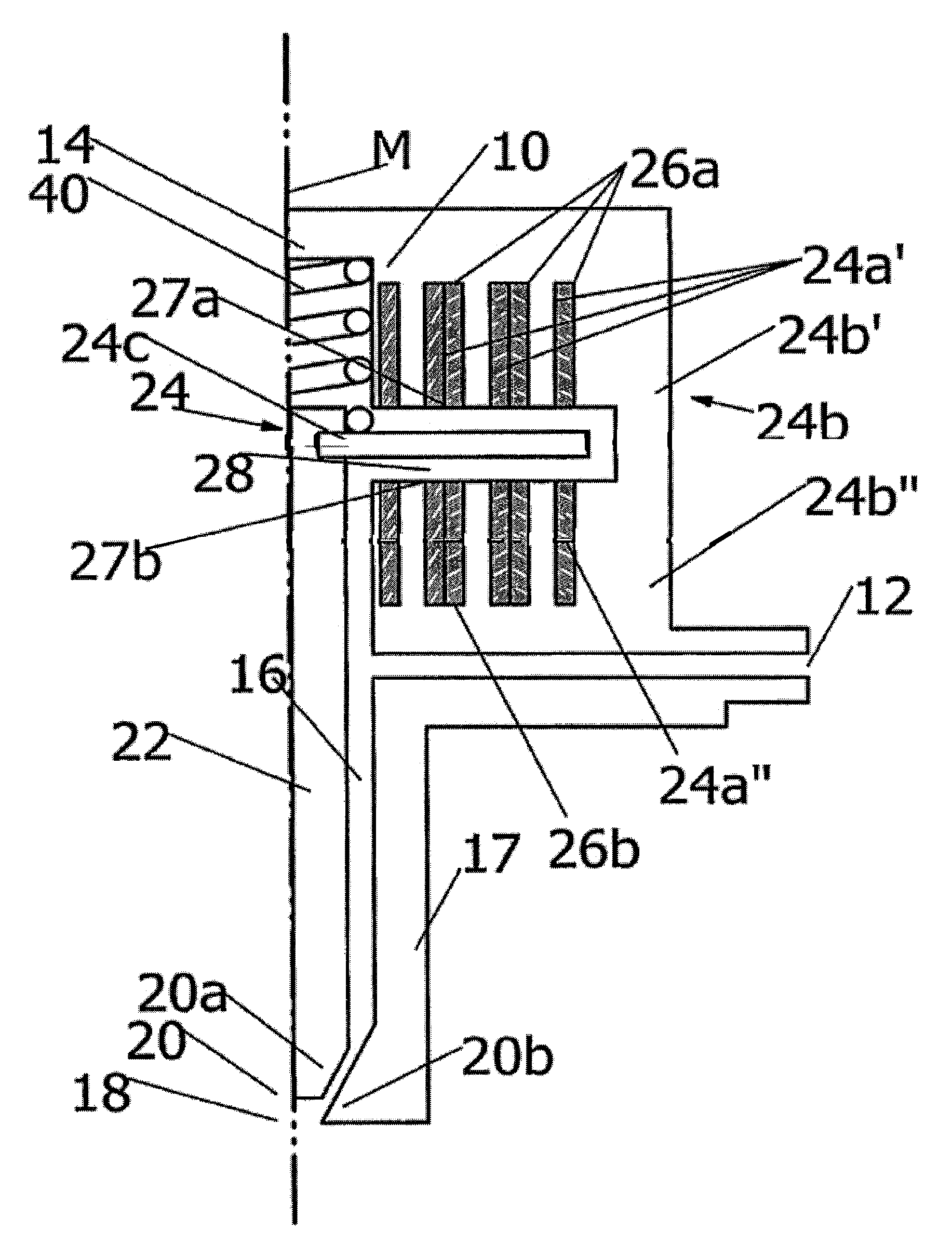
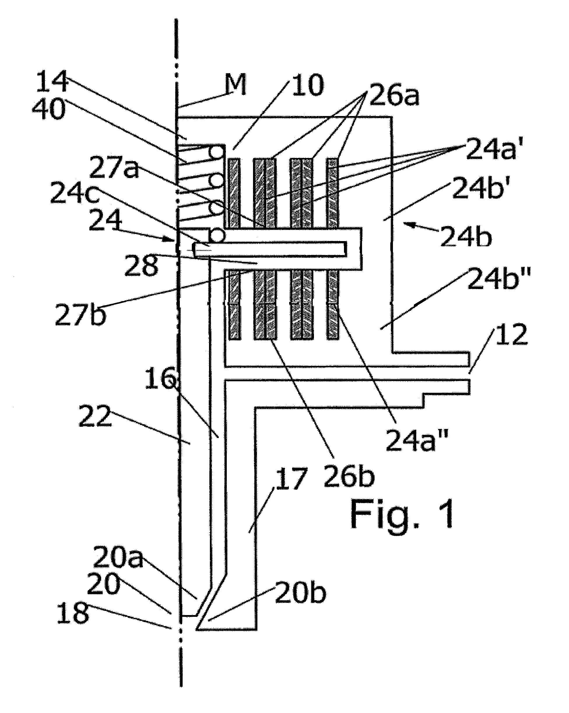
[0057]In FIG. 1, a fuel injection valve, having a valve housing 10 which is substantially rotationally symmetrical in relation to a central longitudinal axis M, is shown in a schematic longitudinal section, in a half-open position. Such a fuel injection valve serves to inject fuel directly into the combustion chamber, not illustrated further, of an internal combustion engine. The fuel injection valve 10 has a radially oriented lateral fuel inlet 12, through which fuel, pressurized by means of a pump or other pressure generator that is not illustrated further, can flow into the fuel injection valve. It is also possible, however, for the fuel inlet to be provided, for instance, in the region of the fuel injection valve that in FIG. 1 is the central, upper region denoted by 14 From the fuel inlet 12, a central fuel channel 16 extends through a tube 17 to a fuel outlet 18. A valve arrangement 20 is provided at the end of the central fuel channel 16, in order to discharge the fuel into t...


PUM

PropertyMeasurementUnit
lengthaaaaaaaaaa
operating pressuresaaaaaaaaaa
dimensionaaaaaaaaaa

Abstract

A fuel injection valve for fuel injection systems of internal combustion engines, in particular for injecting fuel directly into a combustion chamber of an internal combustion engine, said fuel injection valve comprising a fuel inlet which is designed to allow fuel to flow into the fuel injection valve, and an actuating device which can be electrically activated and cooperates with a valve arrangement in order to discharge fuel into the combustion chamber in a directly or indirectly controlled manner via a fuel outlet the actuating device having a solenoid arrangement which is to be energized, a substantially magnetically soft magnet yoke arrangement which cooperates therewith, and a substantially magnetically soft magnet armature arrangement which cooperates therewith. The magnet yoke arrangement is constituted by at least two yoke discs. At least one of the faces of each yoke disc has at least one pole web which together with the solenoid arrangement acts upon the magnet armature arrangement. Each yoke disc is composed of at least two partial yokes which contain soft iron and at least partly surround an actuating rod which supports the magnet armature arrangement.

Description

BACKGROUND OF THE INVENTION[0001]The invention relates to a fuel injection valve for fuel injection systems of internal combustion engines, in particular for injecting fuel directly into a combustion chamber of an internal combustion engine. Basically, it is possible for the invention to be used both in the case of directly injecting engines and in the case of conventional engines that inject into the induction pipe.[0002]The fuel injection valve according to the invention has a fuel inlet which is designed to allow fuel to flow into the fuel injection valve, and an actuating device which can be electrically activated and cooperates with a valve arrangement in order to discharge fuel into the combustion chamber in a directly or indirectly controlled manner via a fuel outlet. The electromagnetic actuating device in this case has a solenoid arrangement which is to be energized, a substantially magnetically soft magnet yoke arrangement which cooperates therewith, and a substantially ma...

Claims


Application Information

Patent Timeline
Patent Type & Authority Patents(United States)
IPC IPC(8): B05B1/30F16K31/02F02M51/00F02M45/08F02M51/06F02M61/16F02M63/00H01F7/16
CPCF02M45/08F02M51/0621F02M51/0653F02M61/166F02M61/168H01F7/1638F02M2200/30H01F7/081H01F2007/1676H01F2007/1692
Inventor GRUNDL, ANDREASHOFFMANN, BERNHARD
Owner COMPACT DYNAMICS
Why Eureka
Try Eureka