
Electrochemical gas sensor and process for manufacturing same

Inactive Publication Date: 2006-02-02
DRAGER SAFETY
View PDF8 Cites 18 Cited by
  • Summary
  • Abstract
  • Description
  • Claims
  • Application Information

AI Technical Summary

Benefits of technology

[0009] The basic object of the present invention is to provide an electrochemical gas sensor that is less bulky and can be assembled easily, which can be assembled from a small number of individual components, has long-term stability and whose mechanical design permits its use in a broad range of environmental humidities.
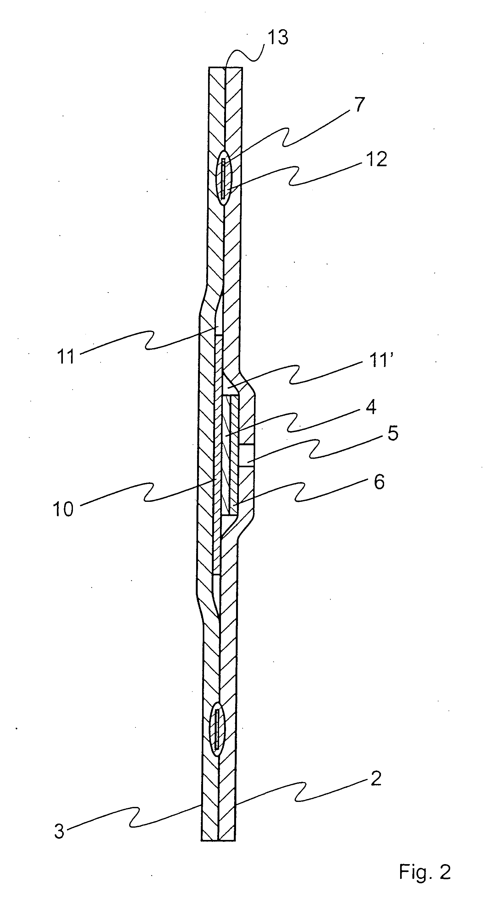
[0010] The present invention is based on the fact that it is possible to further simplify planar sensor structures. Planar electrodes and planar electrolyte carriers can be combined such that they have, on the whole, geometrically smaller dimensions than the housing surrounding the planar electrodes and the planar electrolyte carriers. If they are embedded in a sandwich-like manner in a housing structure that comprises a housing upper part and a housing lower part, it becomes possible, if the housing parts have sufficiently large dimensions, to allow areas of the housing parts to come directly into contact. Simple connection mechanisms can thus be used to connect the housing upper part with the housing lower part and to encapsulate the structure comprising electrodes and electrolyte carrier. It was found that sufficient strength and flexural strength of the sensors according to the present invention can thus be achieved without the additional need for circumferential frame structures for reinforcement. The use of surface areas that are in contact with each other between the housing upper part and the housing lower part makes possible a large number of especially simple assembly variants. Any escape of electrolyte is prevented from occurring with certainty at least in the connection area between the housing parts if the housing parts are connected along a closed figure, which encloses all other components of the sensor, and contact paths are not led through the connection area.
[0011] The requirements that are imposed on the material of the housing are the inert character of this material to ensure that no interactions will take place with the electrolyte or the electrodes; an at least noncontinuous electric volume conductivity in order to allow the electrodes to communicate with one another exclusively via electrolytes and to avoid short-circuits; a low minimum flexibility due to the nature of the construction at least during the connection of the housing upper part and the housing lower part, as well as availability at a low cost. These requirements are met in an excellent manner by numerous planar materials, especially plastics, but also thin glasses. These materials can also be processed, their dimensions can be changed, and they can be provided with openings that may become necessary for electrochemical sensors before or after the assembly without problems.

Problems solved by technology

Thus, the size of these sensors hinders the further spread of the use of electrochemical gas sensors despite the possibility of the adequately reproducible measurement of a great variety of gas components.
Another drawback of prior-art electrochemical gas sensors is the great effort that is needed for their assembly.
The relatively complicated structure of the housing remains as a possibly limiting drawback in the above-described embodiment.
The drawback of the solution being presented here is, however, that the electrodes are contacted by the connection area between the housing parts.
Even though the structure of the initial porous contact material is changed during the connection of the housing parts such that the diffusion of the electrolyte is greatly reduced, experience has shown that it is not possible to find a solution that would be stable over the long term in this manner.

Method used


Image

  • Electrochemical gas sensor and process for manufacturing same
  • Electrochemical gas sensor and process for manufacturing same
  • Electrochemical gas sensor and process for manufacturing same

Examples


Embodiment Construction

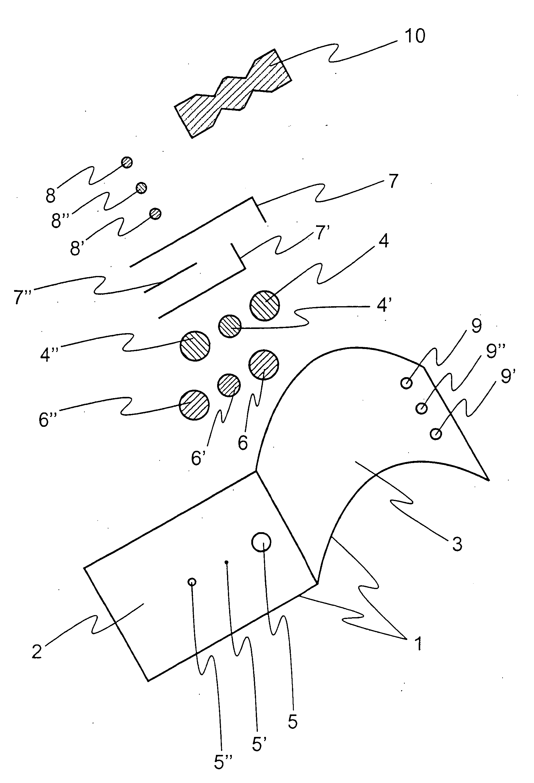
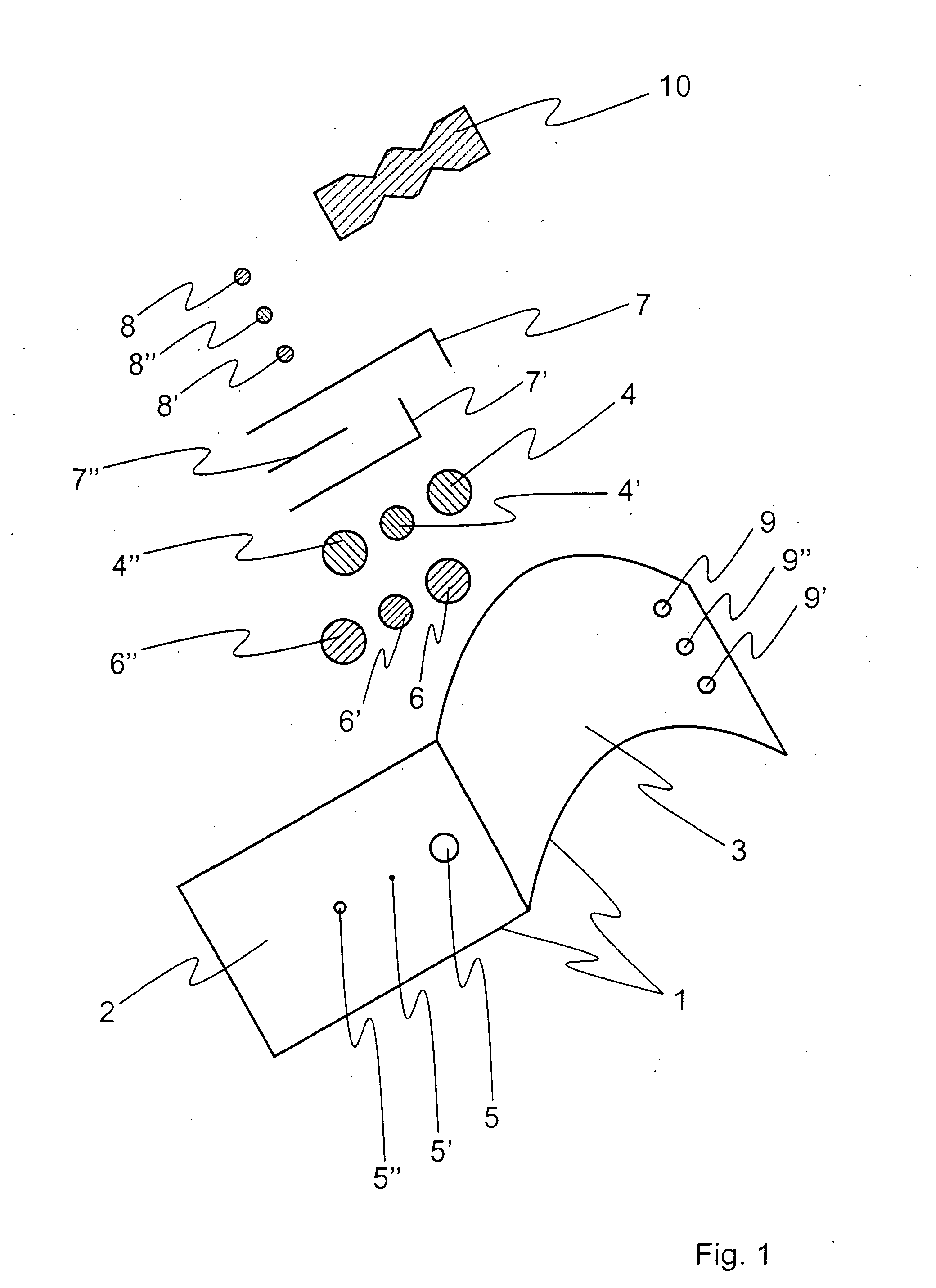
[0032] Referring to the drawings in particular, FIG. 1 shows a complete gas sensor according to the present invention in the form of an exploded view before assembly. It comprises a film pocket 1, comprising the later housing lower part 2 and the later housing upper part 3. Openings 5, 5′, 5″ are present in this film pocket 1 in the area of the housing lower part 2, above which the electrodes 4, 4′, 4″ are arranged, which can be used as a working electrode 4, a counterelectrode 4″ and a reference electrode 4′. The largest opening 5 is used for the entry of the gas to be detected to the working electrode 4. The other openings 5′ and 5″ are used to supply the other two electrodes 4′ and 4″ with oxygen, the opening 5′ for supplying the reference electrode 4′ with oxygen being frequently eliminated. To prevent the electrolyte from escaping, the openings 5, 5′, 5″ are covered with membranes 6, 6′, 6″, which are permeable to the gas but are electrolyte-proof To avoid slipping during the a...


PUM

PropertyMeasurementUnit
Forceaaaaaaaaaa
Volumeaaaaaaaaaa
Areaaaaaaaaaaa

Abstract

A planar electrochemical gas sensor is provided with at least one working electrode (4), at least one counterelectrode (4″), at least one electrolyte-filled planar electrolyte carrier (10), at least one planar housing upper part (3) and at least one planar housing lower part (2). The electrodes (4, 4″) are arranged such that they are in two-dimensional contact with the electrolyte carrier (10). The housing upper part (3) and the housing lower part (2) are connected with one another such that the electrodes (4, 4″) and the electrolyte carrier (10) are pressed against one another in such a way that they are secured against displacement. The housing upper part (3) and the housing lower part (2) are partially in direct two-dimensional contact with one another, and the connection of the housing upper part (3) and the housing lower part (2) in the area of the direct two-dimensional contact is present at least along a closed figure, which surrounds the electrodes (4, 4″) and the electrolyte carrier (10).

Description

CROSS REFERENCE TO RELATED APPLICATIONS [0001] This application claims the benefit of priority under 35 U.S.C. § 119 of German Application DE 10 2004 037 312.4 filed Jul. 31, 2004, the entire contents of which are incorporated herein by reference. FIELD OF THE INVENTION [0002] The invention relates generally to electrochemical gas sensors and more particularly to electrochemical gas sensors that are less bulky and to a process for easily assembling such electrochemical gas sensors. BACKGROUND OF THE INVENTION [0003] Electrochemical gas sensors are suitable for detecting chemical components in gases. Possible uses of gas sensors according to the present invention are found in fields of use of conventional electrochemical gas sensors as well as in fields of use in which the use of such sensors has not hitherto been possible for reasons related to size. [0004] Due to their principle of action, electrochemical gas sensors contain a plurality of electrodes, which communicate with one ano...

Claims


Application Information

Patent Timeline
IPC IPC(8): G01N27/26G01N27/49
CPCY10T29/49002G01N27/404G01N27/49G01N33/00
Inventor METT, FRANK
Owner DRAGER SAFETY
Learn More