
Vehicle body structure

a technology for vehicles and body parts, applied in the direction of electric devices, battery/fuel cell control arrangements, electric devices, etc., can solve the problems of reduced rear trunk capacity, inability to efficiently accommodate electric storage devices, and increased structure size in front/rear direction, so as to reduce the wind resistance created during vehicle travel

Inactive Publication Date: 2009-11-10
HONDA MOTOR CO LTD
View PDF39 Cites 85 Cited by
  • Summary
  • Abstract
  • Description
  • Claims
  • Application Information

AI Technical Summary

Benefits of technology

The present invention provides a vehicle body structure that allows for efficient use of space and effective protection of a storage battery and fuel tank. The structure includes a vehicle body frame and a subframe mounted on the frame. The subframe has side frames, a front cross member, an intermediate cross member, and a rear cross member that allow for the mounting of a storage battery and fuel tank. The subframe also has a support member that allows for easy mounting of the storage battery and a suspension member for supporting a wheel. The structure also includes a front subframe and an intermediate subframe for mounting a fuel cell and a drive motor, respectively. The storage battery may be divided into left and right batteries, and a conductor is used to connect them. An exhaust pipe is also included to protect the battery and reduce wind resistance. Overall, the vehicle body structure provides efficient use of space, effective protection of the battery and tank, and improved performance of the fuel cell vehicle.

Problems solved by technology

There is therefore a problem in that the size of the structure increases in the front / rear direction and the electric storage devices cannot be efficiently accommodated.
However, in the arrangement structure 231 of the electric storage device of the prior art, there is a problem in that the rear trunk capacity is reduced by the electric storage device 233 disposed behind the rear seat 232.
Also, placing the electric storage device 233 in an upright orientation behind the rear seat 232 creates a problem whereby the position of the center of gravity of the vehicle is elevated in comparison with a structure in which the electric storage device is disposed on the bottom side of the vehicle body.

Method used


Image

  • Vehicle body structure
  • Vehicle body structure
  • Vehicle body structure

Examples


Embodiment Construction

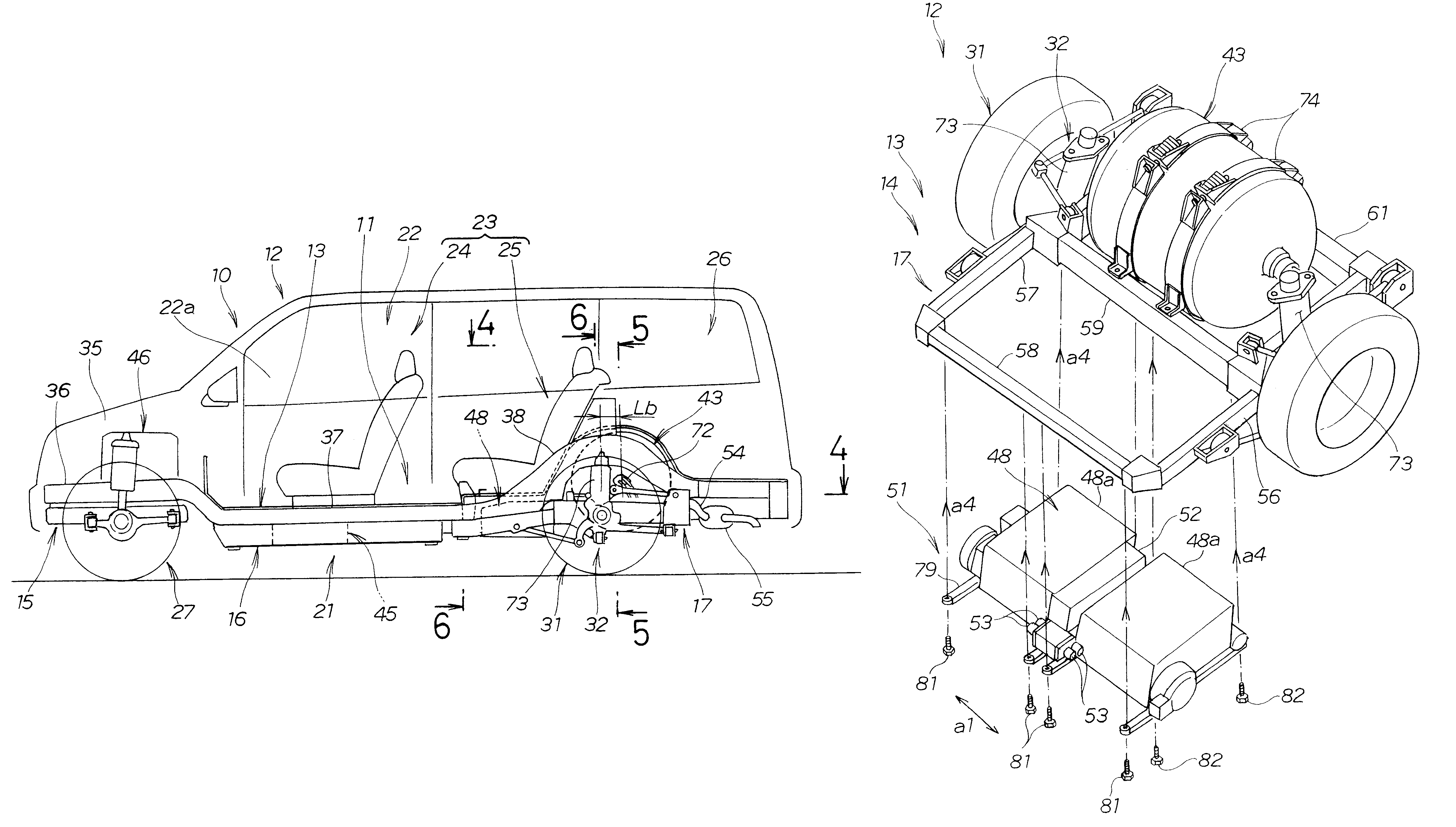
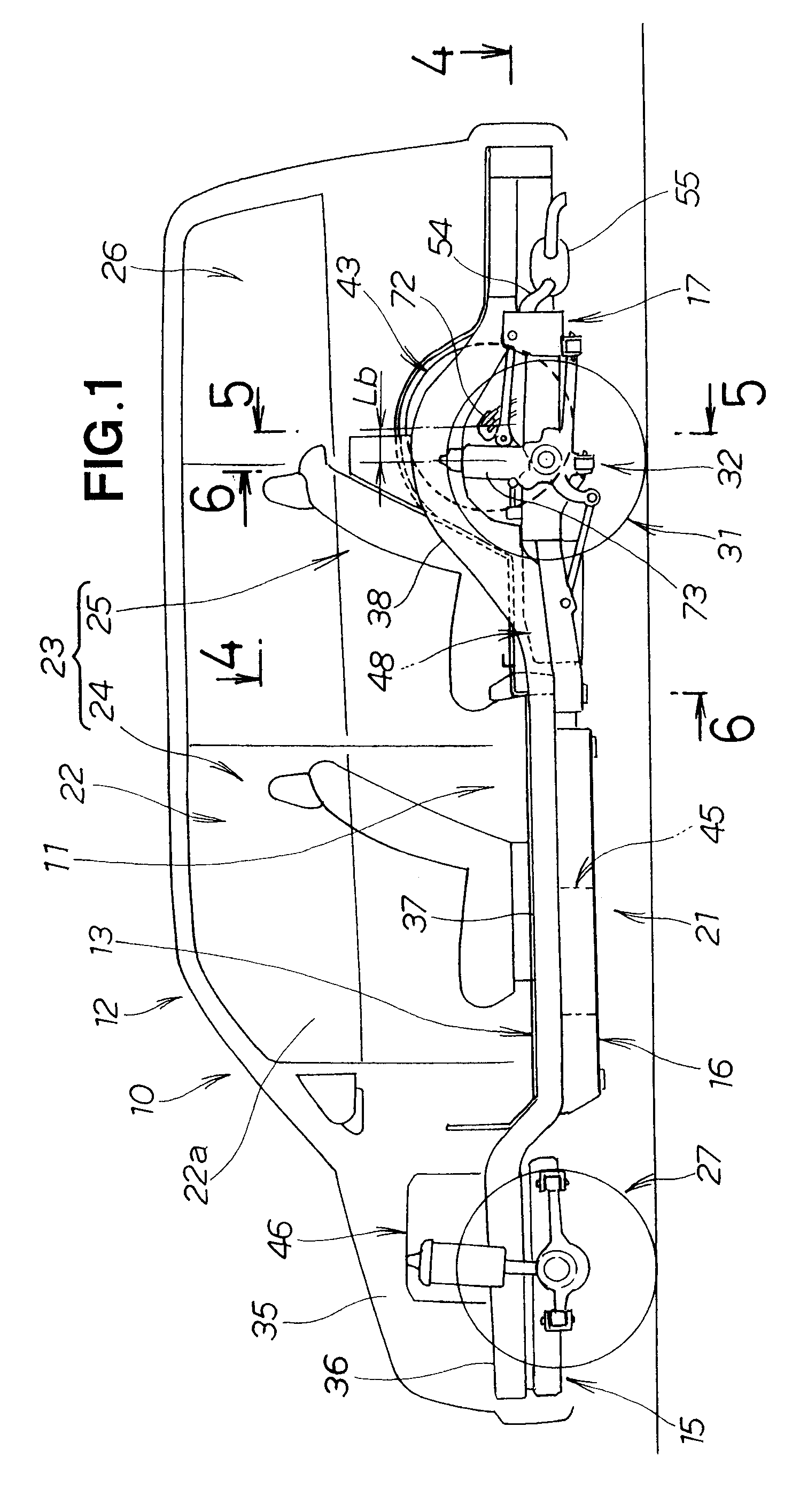
[0036]The vehicle 10 shown in FIG. 1 is a fuel cell vehicle. The vehicle 10 is provided with the vehicle body structure 11 of the present invention, a fuel cell system 21, seats 23 comprising a front seat 24 and a rear seat 25 disposed in the vehicle interior 22, a luggage compartment 26, front wheels 27, rear wheels 31, and a rear suspension 32. The front seat 24 is disposed in the cabin 22a of the vehicle interior 22.

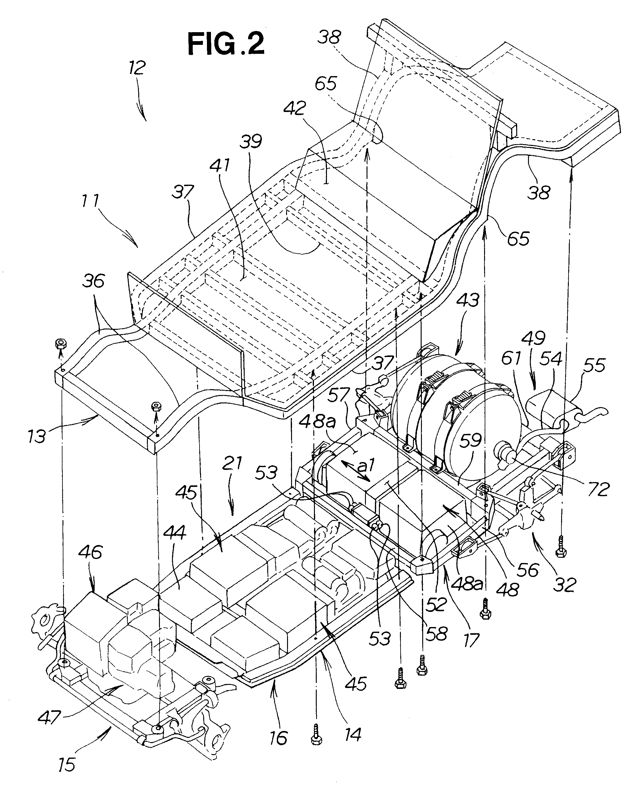
[0037]The vehicle body structure 11 constitutes a portion of the vehicle body 12 and comprises a vehicle body frame 13 that extends in the front / rear direction of the vehicle 10, and a subframe 14 mounted in the lower portion of the vehicle body frame 13. The subframe 14 comprises a front subframe 15, an intermediate subframe 16, and a rear subframe 17.

[0038]FIG. 2 shows a vehicle body frame 13 provided with the vehicle body structure 11 of the present invention.

[0039]The vehicle body frame 13 is provided with left and right side frames 36 and 36, left and right side ...


PUM


Abstract

A vehicle body structure includes a body frame with a subframe mounted to a lower part of the body frame. The subframe is formed into a rectangular shape and has front, intermediate and rear cross members. A storage battery is designed to be mounted astride the front cross member and the intermediate cross member. A fuel tank is designed to be mounted astride the intermediate cross member and the rear cross member.

Description

FIELD OF THE INVENTION[0001]The present invention relates to a vehicle body structure in which a compressed gas fuel tank and a storage battery are disposed on a vehicle body frame.BACKGROUND OF THE INVENTION[0002]Vehicle body frames are provided with a subframe mounted in the lower portion of the frame, and compressed gas fuel tanks and storage batteries are disposed on the subframe. The vehicle body structure disclosed in Japanese Patent Laid-Open Publication No. 2004-291934, for example, is described below with reference to FIG. 9 hereof.[0003]FIG. 9 is a diagram that describes the prior art. Since the conventional vehicle body structure 201 has a configuration in which electric storage devices 204 and 205 and hydrogen tanks (compressed gas fuel tank) 206 and 207 are mounted on a subframe 203, and the subframe is mounted on a floor main frame 202, assembly is facilitated and vehicle interior space and trunk capacity can be expanded.[0004]However, in the above-described convention...

Claims


Application Information

Patent Timeline
Patent Type & Authority Patents(United States)
IPC IPC(8): B60K1/00B60K6/32
CPCB60K1/04B62D21/11B60K2001/0416Y02T90/34B60K2001/0472B60K2001/0433B60L1/003B60L15/20B60L2220/46B60L2240/423B60L50/52B60L50/66B60L50/71B60L50/72B60L58/21B60L58/40Y02T10/64Y02T10/70Y02T10/72Y02T90/40
Inventor ONO, TOHRUSUGAWARA, TAKAHIROOGAWA, TAKAYUKIYAMAMOTO, KOICHI
Owner HONDA MOTOR CO LTD
Learn More