Lock fixing mechanism with quick assembly and disassembly and a booth applied with the mechanism

Active Publication Date: 2017-01-05
SUNTOP XIAMEN DISPLAY SYST
View PDF1 Cites 1 Cited by
  • Summary
  • Abstract
  • Description
  • Claims
  • Application Information

AI Technical Summary

Benefits of technology

The present invention provides a lock fixing mechanism that can be easily and quickly assembled and disassembled without additional tools. It is stable and reliable with a main body and a movable connector that can be easily connected and disconnected by rotating the connecting element. Additionally, a position lock bar and guiding device are provided for smooth motion.

Problems solved by technology

Traditional good shelf and booth are composed of lateral pipes and longitudinal pipes, it usually applies lap joints or screws to connect the pipes, the assembly method is complicated, it needs additional tools to assemble, it is also complicated to disassemble, it also needs professional to operate that it is of time waste and labor waste.

Method used


Image

  • Lock fixing mechanism with quick assembly and disassembly and a booth applied with the mechanism
  • Lock fixing mechanism with quick assembly and disassembly and a booth applied with the mechanism
  • Lock fixing mechanism with quick assembly and disassembly and a booth applied with the mechanism

Examples


first embodiment

The First Embodiment

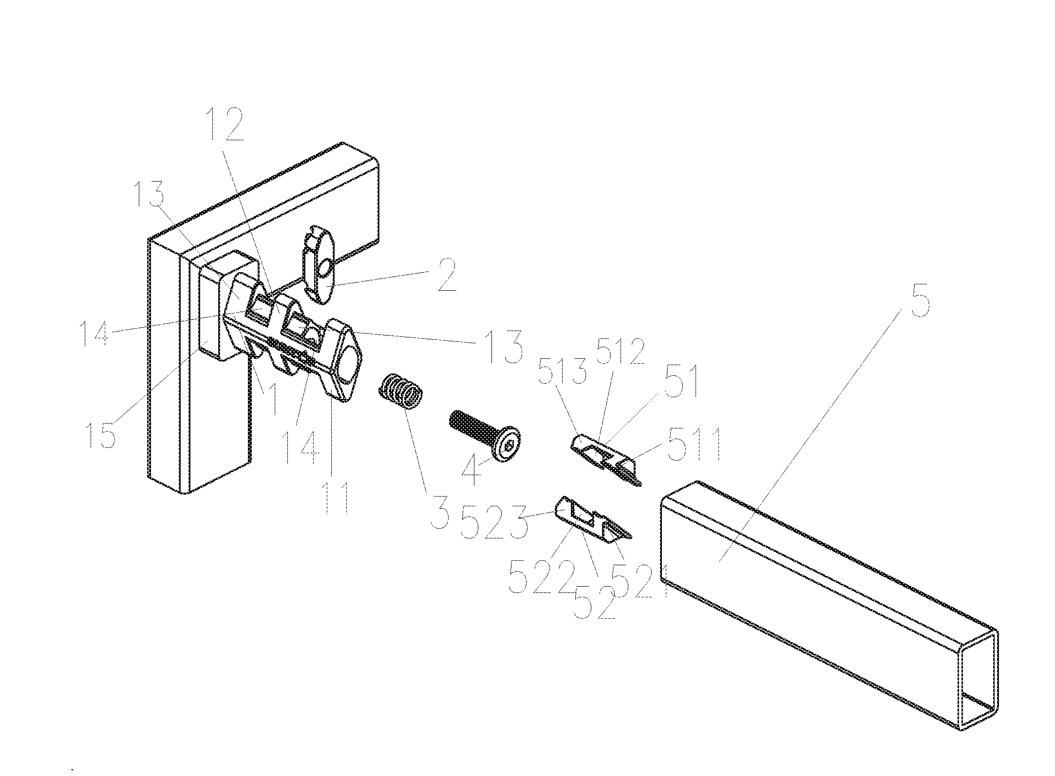
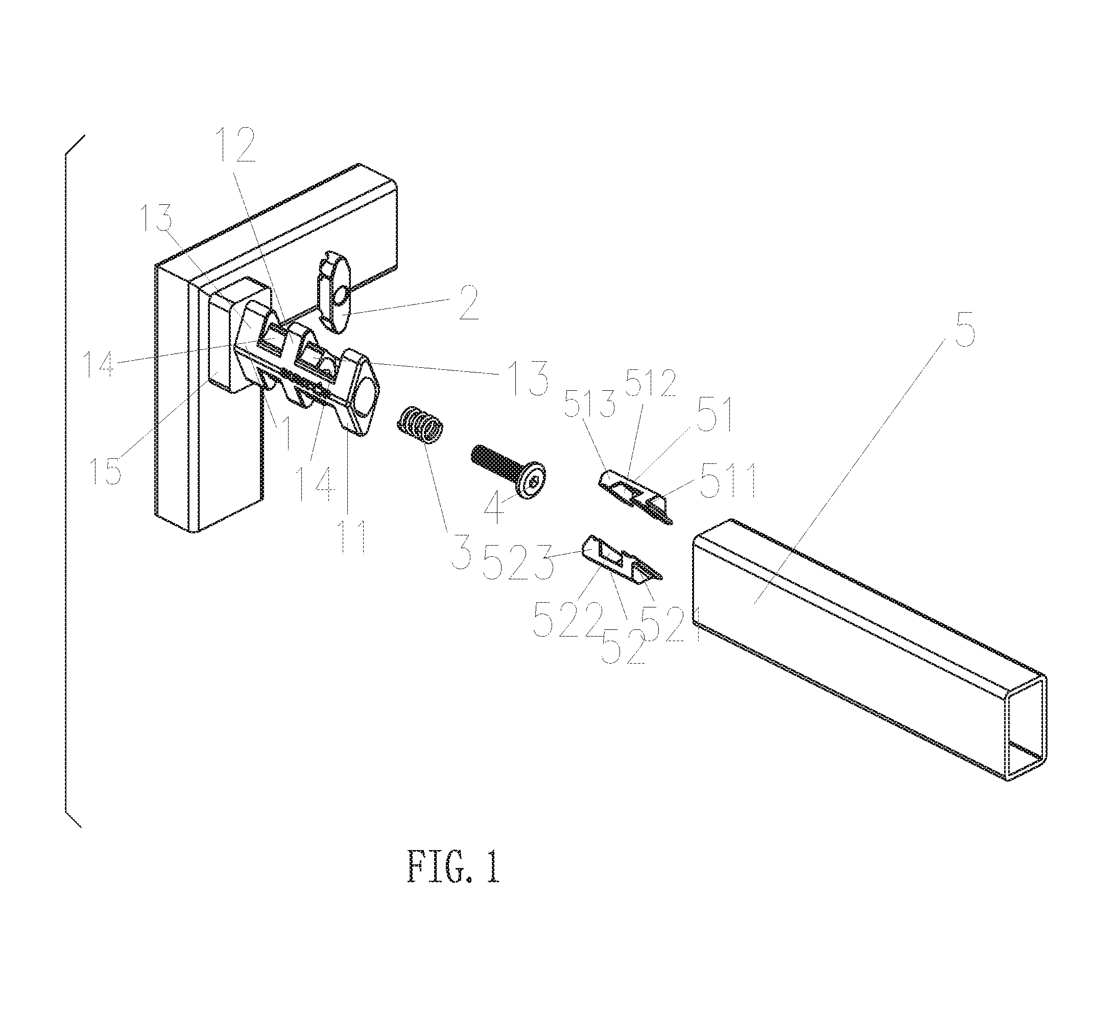
[0027]Referring to FIG. 1, a lock fixing mechanism with quick assembly and disassembly comprises:

a lock fixing mechanism main body 1, the main body 1 is disposed with a front end portion 11 and a first boss 12, the front end portion 11 is connected to the central portion of a side surface of the first boss 12; a chamber 14 is formed between the front end portion 11 and the first boss 12; in this embodiment, the section of the front end portion 11 and the first boss 12 in the direction vertical to the assembly direction are rhombus shaped with same size.

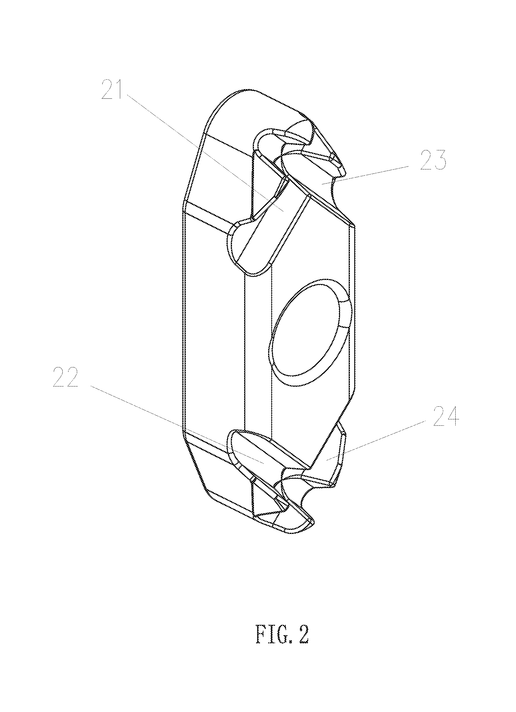
[0028]A position lock block 2, the position lock block 2 is disposed in the chamber 14; one side of the position lock block 2 near the first boss 12 is disposed with a first groove 21 and a second groove 22, the first groove 21 and the second groove 22 are symmetrical about the center; in this embodiment, the first groove 21 and the second groove 22 are of same size and shape, they are incline groove bars with heig...

second embodiment

The Second Embodiment

[0034]Referring to FIG. 1, this embodiment differs from the first embodiment in that: the position lock block 2 and the elastic device 3 are assembled between the front end portion 11 and a first guiding device 13 by a screw 4, so that the position lock block 2 and the elastic device 3 would not move in the vertical direction.

[0035]The rest portion of this embodiment is similar to the first embodiment that it would not be further described.

third embodiment

The Third Embodiment

[0036]Referring to FIG. 1, this embodiment differs from the second embodiment in that: one end of the first lock groove 512 away from the first lock fixing component 511 is disposed with a first guiding block 513. One end of the second lock groove 522 away from the second lock fixing component 521 is further disposed with a second guiding block 523. At the same time, the main body 1 is further disposed with a first guiding device 13 and a third boss 14. The first guiding device 13 is disposed between the position lock block 2 and the first boss 12 and is fixedly connected to the first boss 12. The third boss 14 is connected to the central portion of the side surface of the first boss 12; a second guiding device 15 is disposed between the third boss 14 and the second boss 12.

[0037]With the first guiding block 513, the second guiding block 523 and the first guiding device 13, the second guiding device 15, when the movable connector 5 is sleeved on the main body 1, ...


PUM


Abstract

The present invention is provided with a lock fixing mechanism with quick assembly and disassembly, with a position lock block coupled to a position lock bar, the position lock block is contacted with the side surface of the position lock bar, by rotating, the position lock block squeezes the position lock bar. Under the action of the pressure, the spring connected to the position lock block deforms that the position lock bar moves towards the deforming direction of the spring, therefore the position lock bar is locked between the position lock block. The entire device doesn't need additional components nor need professional to operate that it has well applicability. The present invention further provides with a booth applied with the lock fixing mechanism with quick assembly and disassembly.

Description

FIELD OF THE INVENTION[0001]The present invention relates to a connecting fixing device, especially to a lock fixing mechanism with quick assembly and disassembly and a booth applied with the mechanism.BACKGROUND OF THE INVENTION[0002]Traditional good shelf and booth are composed of lateral pipes and longitudinal pipes, it usually applies lap joints or screws to connect the pipes, the assembly method is complicated, it needs additional tools to assemble, it is also complicated to disassemble, it also needs professional to operate that it is of time waste and labor waste.SUMMARY OF THE INVENTION[0003]The main object of the present invention is to provide with a lock fixing mechanism that can be disassembled and assembled quickly, it doesn't need additional tool to assemble and disassemble, it is convenient and fast.[0004]The second object of the present invention is to provide with a booth applied with above lock fixing mechanism.[0005]The technical proposal of the present invention ...

Claims


Application Information

Patent Timeline
IPC IPC(8): F16B12/10F16B12/40A47B3/06A47B47/00
CPCA47B47/0016A47B47/005F16B12/20F16B12/32F16B12/40F16B2012/103A47B3/06A47F5/00
Inventor LI, HONGZE
Owner SUNTOP XIAMEN DISPLAY SYST
Why Eureka
Try Eureka