Nonmetallic push-in connector

Active Publication Date: 2017-01-19
ANTONUCCI MARK
View PDF5 Cites 0 Cited by
  • Summary
  • Abstract
  • Description
  • Claims
  • Application Information

AI Technical Summary

Benefits of technology

[0016]Furthermore, in a preferred embodiment, the longitudinal protrusions that define the grooves do not run the entire length of the interior of the connector body, i.e., the lead-in end is a hollow cavity without grooves or longitudinal protrusio

Problems solved by technology

First and foremost, it is cumbersome to install.
As a result, the housings are smaller or thinner and make inserting one's hands into the housing to hold or turn the nut that fits onto the lead-in end much more difficult.
Moreover, the connectors must be smaller in diameter to fit into the holes left by the knock-outs, making them more difficult to manipulate.
In addition, when being screwed over the lead-in end, the nut can catch on a flange or lip of the light fixture housing making screwing the nut onto the connector more difficult.
Moreover, since it may be easier to hold the nut in place and turn the rest of the connector during installation, it can be difficult to orient the connector such that it is securely attached to the nut and the screws on the feed end are oriented in a dire

Method used


Image

  • Nonmetallic push-in connector
  • Nonmetallic push-in connector
  • Nonmetallic push-in connector

Examples


Example

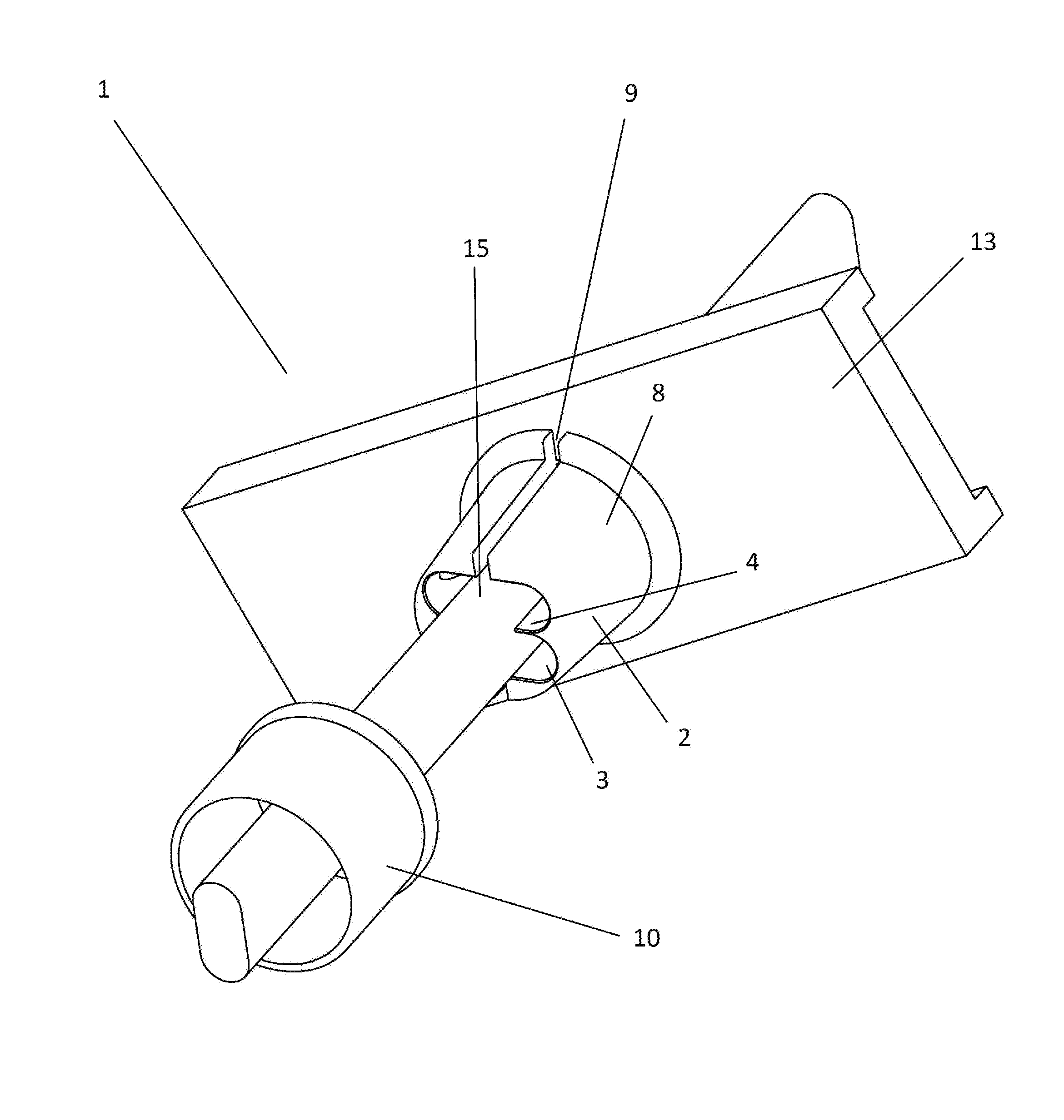
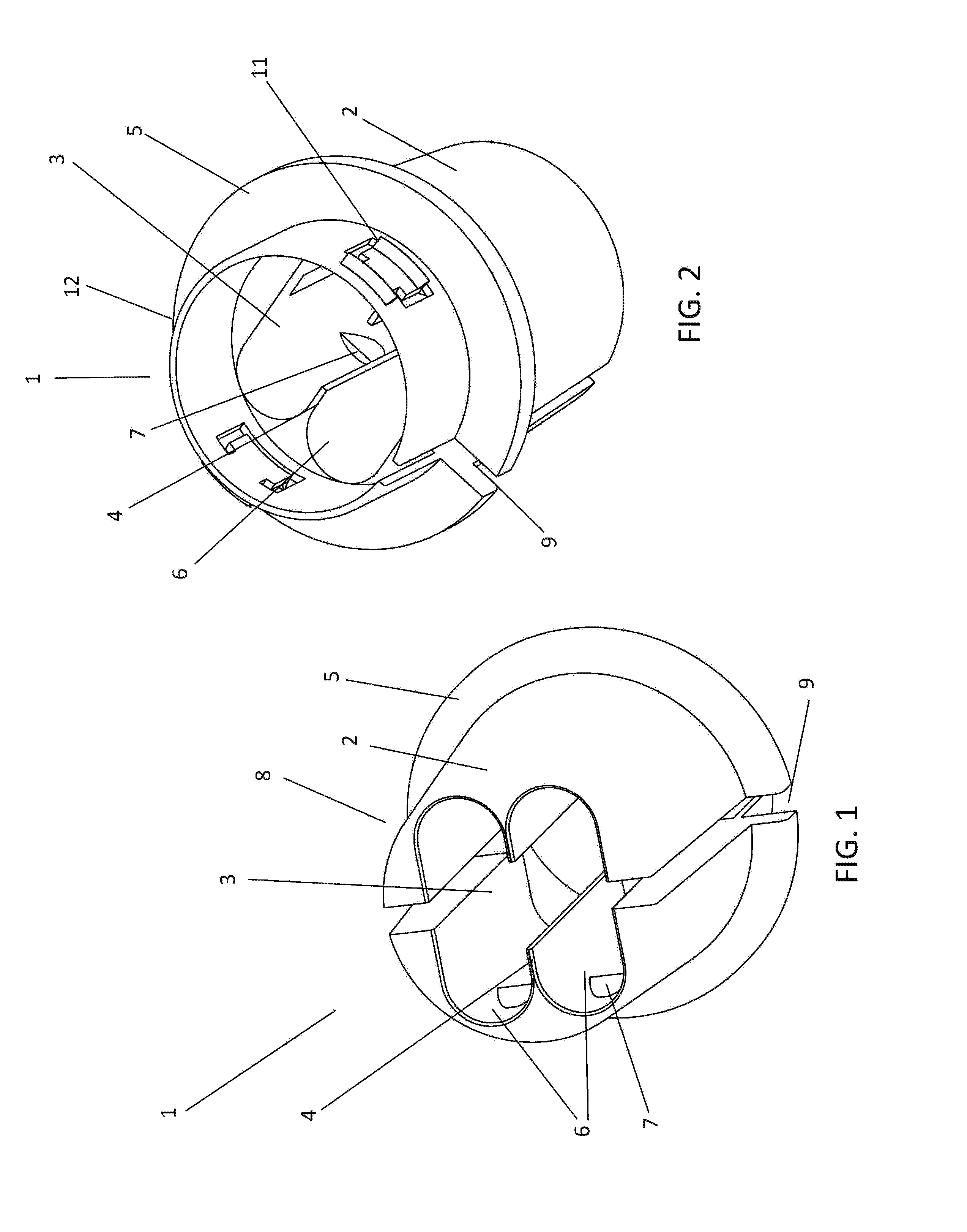
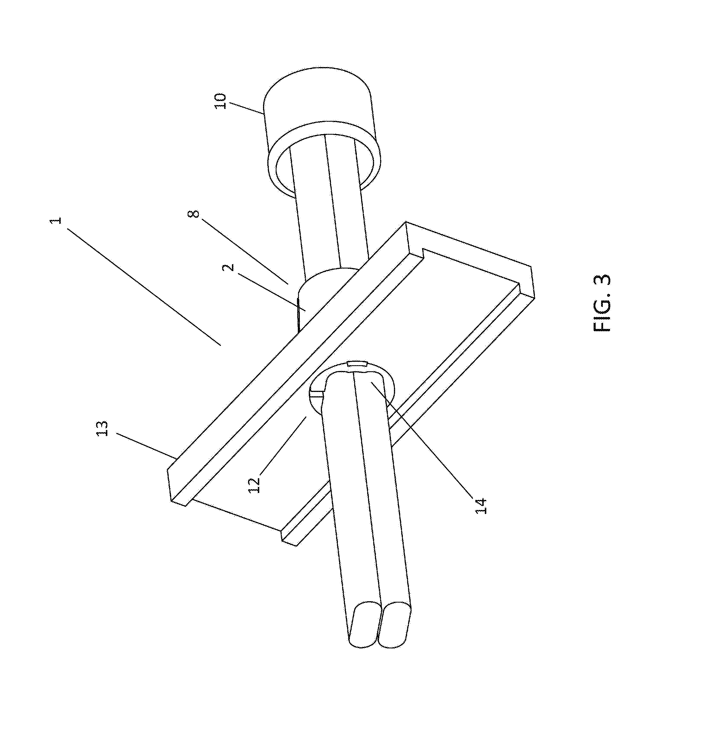
[0026]Referring now to the invention in more detail, FIGS. 1 and 2 show perspective views of an embodiment of the disclosed connector. More specifically, the push-in connector, generally 1, has a body 2. Note, those skilled in the art can immediately appreciate that the body of the connector can be any shape needed to fit into an electrical housing. Since most electrical housings for residential electrical enclosures and lighting fixtures have circular knock-outs, the connector body 2 is shown to be generally cylindrical. FIG. 1 is a perspective view showing the feed end 8 of the connector. FIG. 2 is a perspective view showing the lead-in end of the connector 1. The connector body 2 has an interior channel 3 running the longitudinal length of the connector body 2. In one embodiment of the disclosed connector, the interior channel 3 of the connector body 2 contains one or more longitudinal protrusions 4. The longitudinal protrusions 4 extend longitudinally along at least part of the ...


PUM


Abstract

A push-in connector generally having an interior channel equipped with longitudinal protrusions that run at least part of the length of the interior channel of the connector body to define grooves through which wires of a different gauges can be inserted. When the user rotates the connector body about its longitudinal axis, the interior channel defines a second gauge through which a wire of a second gauge can pass. The connector body has one or more incisions cut into one end of the connector body and a separate cuff that fits over the feed end. The interior channel contains teeth that grip the wire(s) or cable(s) once inserted. The exterior of the connector body has flexible exterior protrusions that can be pushed down when inserting the connector through the knock-out of a housing and spring back into place to secure the connector to the housing.

Description

CROSS-REFERENCE TO RELATED APPLICATIONS[0001]This application claims the benefit of priority to and is a continuation in part of U.S. application Ser. No. 14 / 731,126 filed on Jun. 4, 2015. The content of U.S. application Ser. No. 14 / 731,126 filed on Jun. 4, 2015 is incorporated by reference herein in its entirety.BACKGROUND OF THE INVENTION[0002]1. Field of the Invention.[0003]The present disclosure is in the technical field of connectors used in installing wiring. More specifically, the present disclosure is directed towards a push-in connector commonly used in wiring electrical housings, such as lighting fixtures, wiring compartments, splice boxes, etc. Even more particularly, the present disclosure is directed towards nonmetallic push-in connectors commonly used to install wiring into a residential light fixture, specifically into a fixture featuring a ⅜ inch knock-out.[0004]2. Background Art.[0005]Throughout this specification, specific reference will be made to units of measure...

Claims


Application Information

Patent Timeline
IPC IPC(8): H01B17/58
CPCH01B17/583H01R13/5816H02G3/083H01R13/5837
Inventor ANTONUCCI, MARK
Owner ANTONUCCI MARK
Why Eureka
Try Eureka