Preaction sprinkler valve assemblies, related dry sprinkler devices and fire protection sprinkler systems

a technology of sprinkler valves and assemblies, applied in the field of fire protection, can solve the problems of all must be ordered from and fabricated by manufacturers, and affecting the installation and completion of construction projects. the effect of time and great expense for the installer and the end purchaser

Active Publication Date: 2017-02-02
VICTAULIC
View PDF3 Cites 23 Cited by
  • Summary
  • Abstract
  • Description
  • Claims
  • Application Information

AI Technical Summary

Benefits of technology

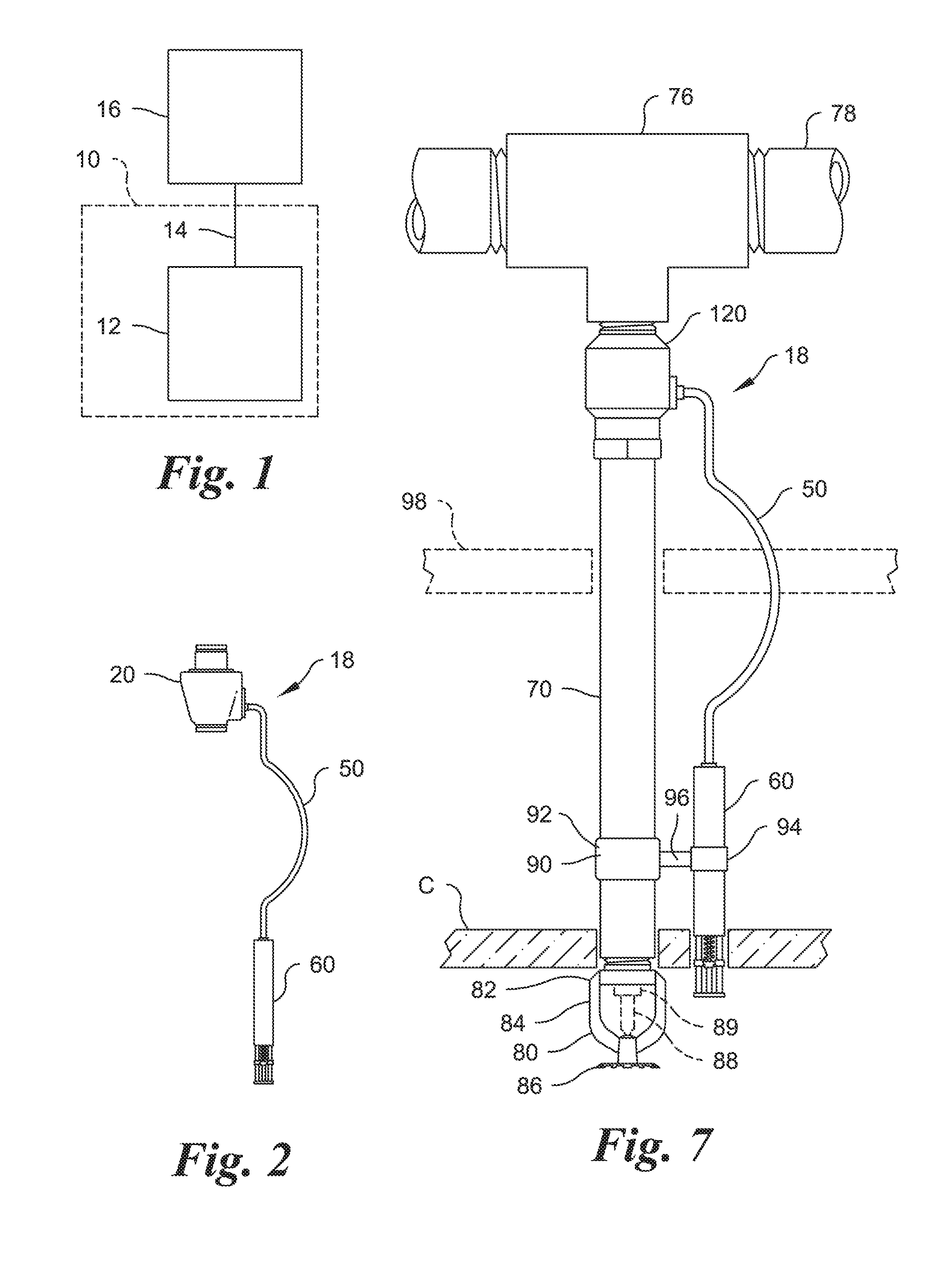
[0026]FIG. 7 is a is a side elevation diagrammatic view of a preaction valve assembly incorporating the second embodiment valve of FIGS. 4-6 ins...

Problems solved by technology

This delays installation and completion of construction projects.
Longer delays occur if mistakes are made in measuring or fabricating the sprinklers or the sprinklers are damaged in transit and replacement sprinklers required, further delaying completion of the installation.
While this arrangement provides some flexibility with respect to installation and fabrication by the installer and manufacturer, it leaves the end user with a complicated pressure regulation system to maintain to assure that pressure in the flexible tube is held at an adequate level to prevent water leakage thr...

Method used


Image

  • Preaction sprinkler valve assemblies, related dry sprinkler devices and fire protection sprinkler systems
  • Preaction sprinkler valve assemblies, related dry sprinkler devices and fire protection sprinkler systems
  • Preaction sprinkler valve assemblies, related dry sprinkler devices and fire protection sprinkler systems

Examples


second embodiment

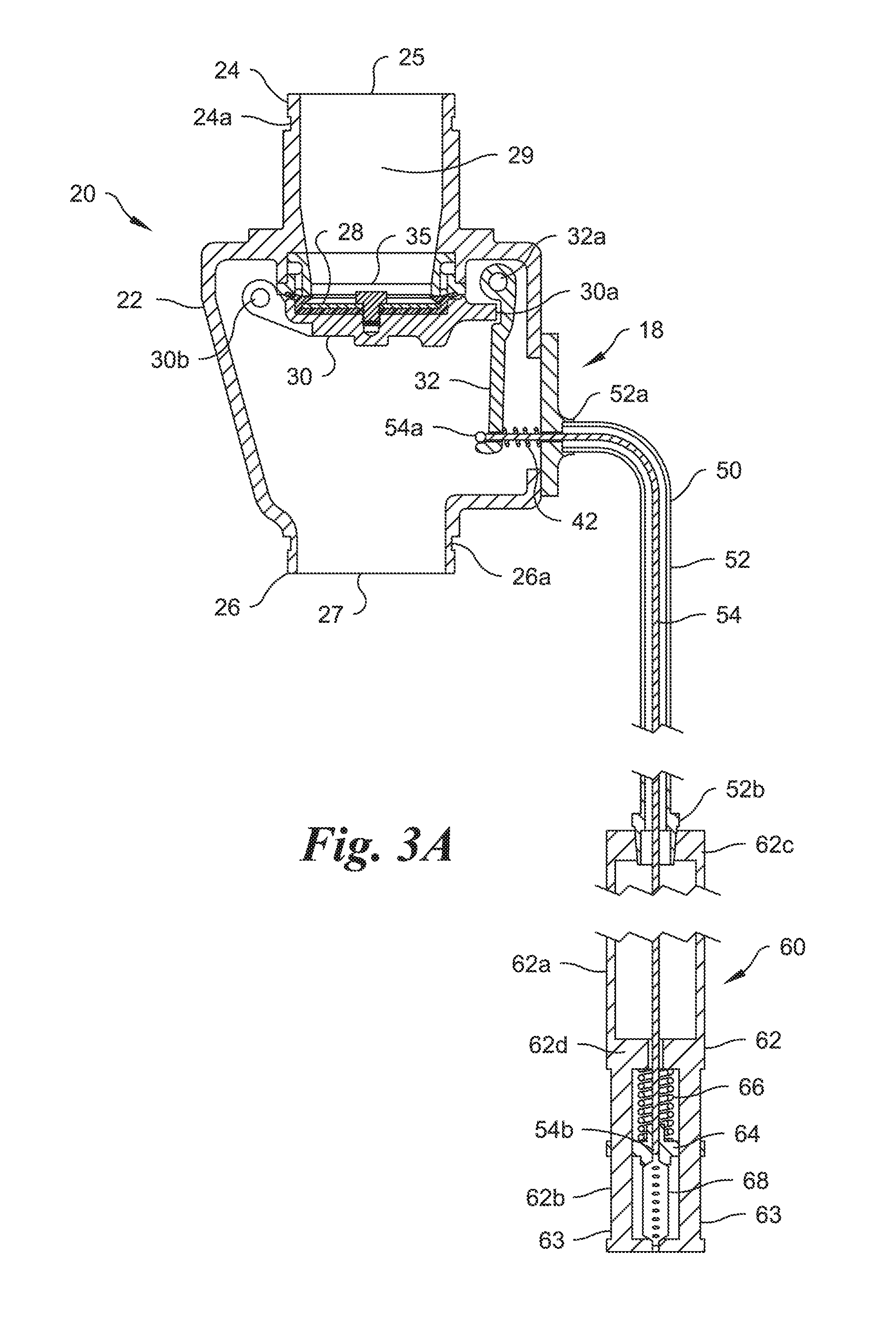
[0044]FIGS. 4-6 depict a valve component 120 of the invention in the form of a poppet valve. The valve component 120 again includes a body 122 with an inlet end 124 externally threaded to be received in a Tee in or a threaded pipe from a wet supply line and an outlet end 126 internally threaded to receive an externally threaded length of piping. A seal member 128 is supported in the inlet 125 by a pivotally mounted lever 130 retained in a “closed” or “supporting” position by a pivotally mounted latch 132. An adjustment screw 134 can be provided in the lever 130 to vary the mechanical compression provided on the seal member 128. Two parallel cross-members 136, 138 span an enlarged central chamber 140 of the body 122 and terminate in a pin 139 received in a bore 122a in an inner side wall of the body 122 distal to a removable cover 123. The cross members 136, 138 support pivots for the lever 130 and the latch 132. A hollow boss 129 formed between the cross members 136, 138 slidably re...

embodiment 1100

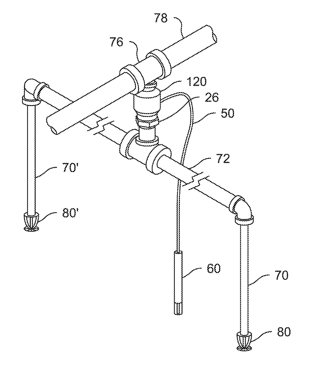
[0060]FIG. 14 depicts a dry sprinkler device embodiment 1100 of the present invention using a thermal trigger assembly 1110 with slightly modified embodiments of a valve component 1120, a flexible connector 1150, and an activation component 1160. The valve component 1120 and proximal end of the flexible connector 1150 are shown in cross section in FIGS. 15-16. The valve component 1120 includes the same body 122 with an inlet end 124 having an inlet 125, which is externally threaded so as to be received in a tee fitting or in another type of fitting connection from a water supply line. An outlet end 126 has an outlet 127, which is internally threaded to receive an externally threaded length of pipe 70 (fabricated by an installer), which receives a conventional, open sprinkler 80. A seal member 128 is again supported in the inlet 125 by a lever 130 retained in a “closed” or “supporting” position by a latch 132. The latch 132 pivots around a latch pivot 132a, which is a pinned connecti...


PUM


Abstract

A thermal trigger assembly for remote mechanical actuation of another fire protection system component includes an activation component having a base and a movable member. A bias member biases the movable member from a preactivation to an activated position with respect to the base. A thermally responsive element retains the movable member in the preactivation position until a predetermined thermodynamic condition is reached, when the thermally responsive element loses structural integrity. A flexible connector includes a flexible hollow outer cable housing with one end configured to be stationarily (preferably fixedly) connected with the base. A flexible cable is inside the outer cable housing for sliding movement therein and has one end configured to be stationarily (preferably fixedly) connected with the movable member. The flexible cable is moved with respect to the outer cable housing by movement of the movable member upon loss of structural integrity by the thermally responsive element.

Description

CROSS-REFERENCE TO RELATED APPLICATIONS[0001]This application claims the benefit of priority under 35 USC §119(e) of U.S. Provisional Patent Applications No. 62 / 304,585 filed Mar. 7, 2016; No. 62 / 267,445 filed Dec. 15, 2015; No. 62 / 198,428 filed Jul. 29, 2015; and No. 62 / 197,927 filed Jul. 28, 2015, the contents of all of which are incorporated herein by reference in their entirety.BACKGROUND OF THE INVENTION[0002]The present disclosure relates generally to fire protection, and, more particularly, to activation components for fire protection systems, and valves for use in fire protection systems.[0003]Fire sprinkler system installation and operation are subject to nationally recognized codes.[0004]As is aptly pointed out in U.S. Patent Application Publication No. 2013 / 0199803, dry sprinklers are used in areas that are or may be exposed to freezing conditions, such as in freezers, unheated internal areas, walkways, etc. In typical dry-pipe systems, supply conduits run in a space wher...

Claims


Application Information

Patent Timeline
IPC IPC(8): A62C37/42A62C37/48A62C35/62
CPCA62C37/42A62C35/62F16K31/465A62C99/0072A62C37/48A62C3/004A62C37/11F16K1/2007F16K31/002
Inventor MEYER, STEPHEN J.RINGER, YORAMARCHIBALD, THOMAS EDWIN
Owner VICTAULIC
Why Eureka
Try Eureka