

Method and apparatus for drying sprinkler piping networks
- Summary
- Abstract
- Description
- Claims
- Application Information
AI Technical Summary
Problems solved by technology
Method used
Image

Examples
Embodiment Construction
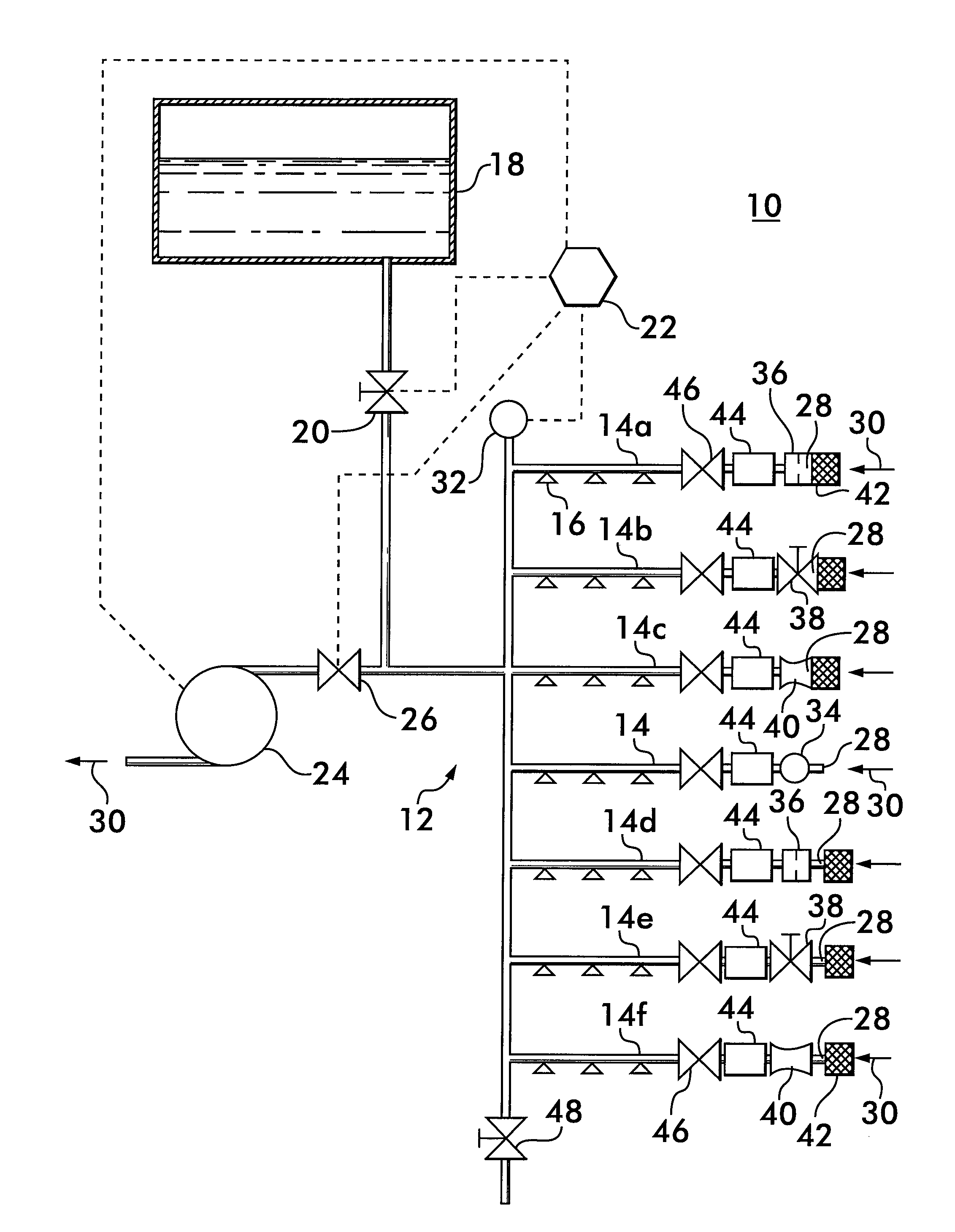
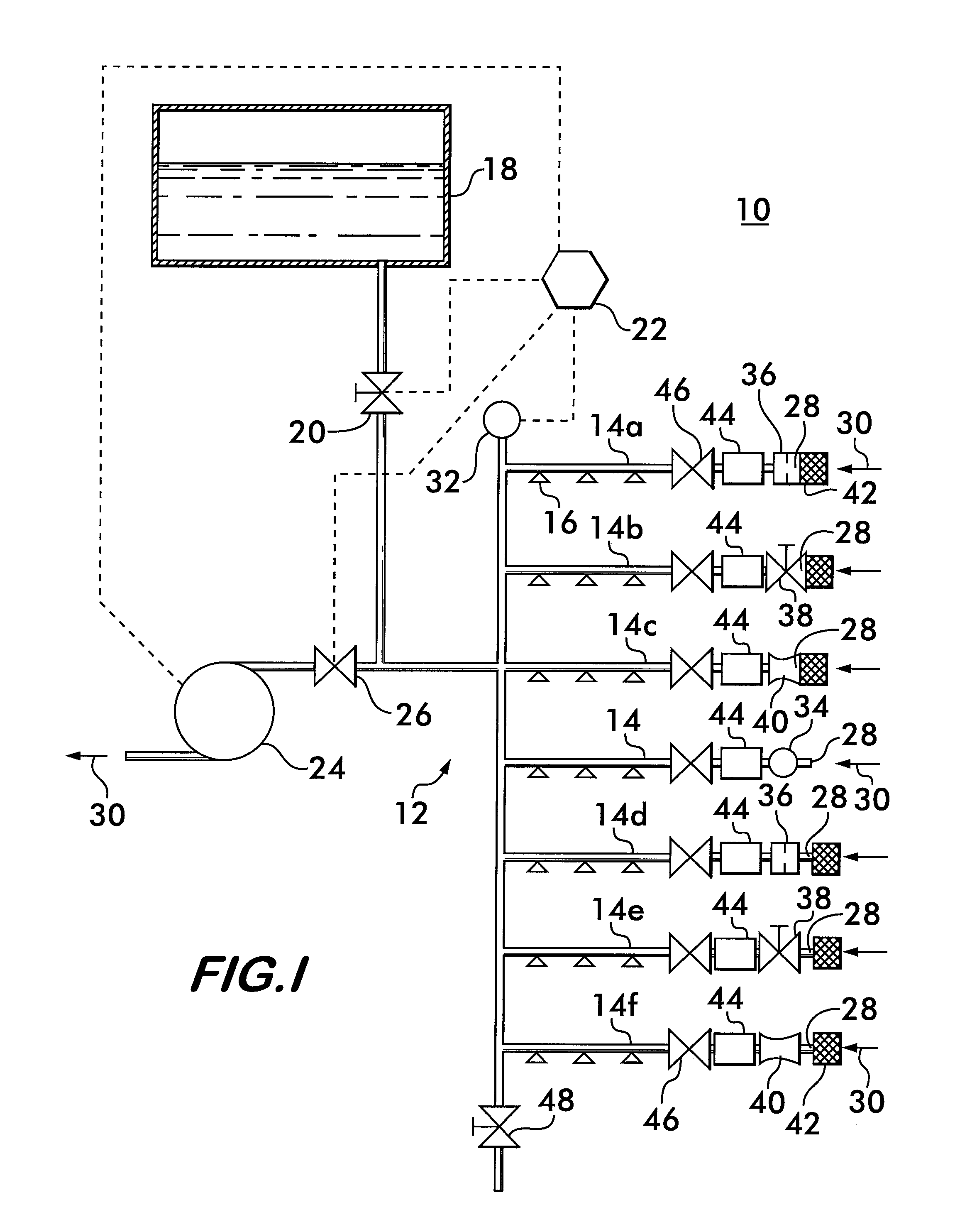
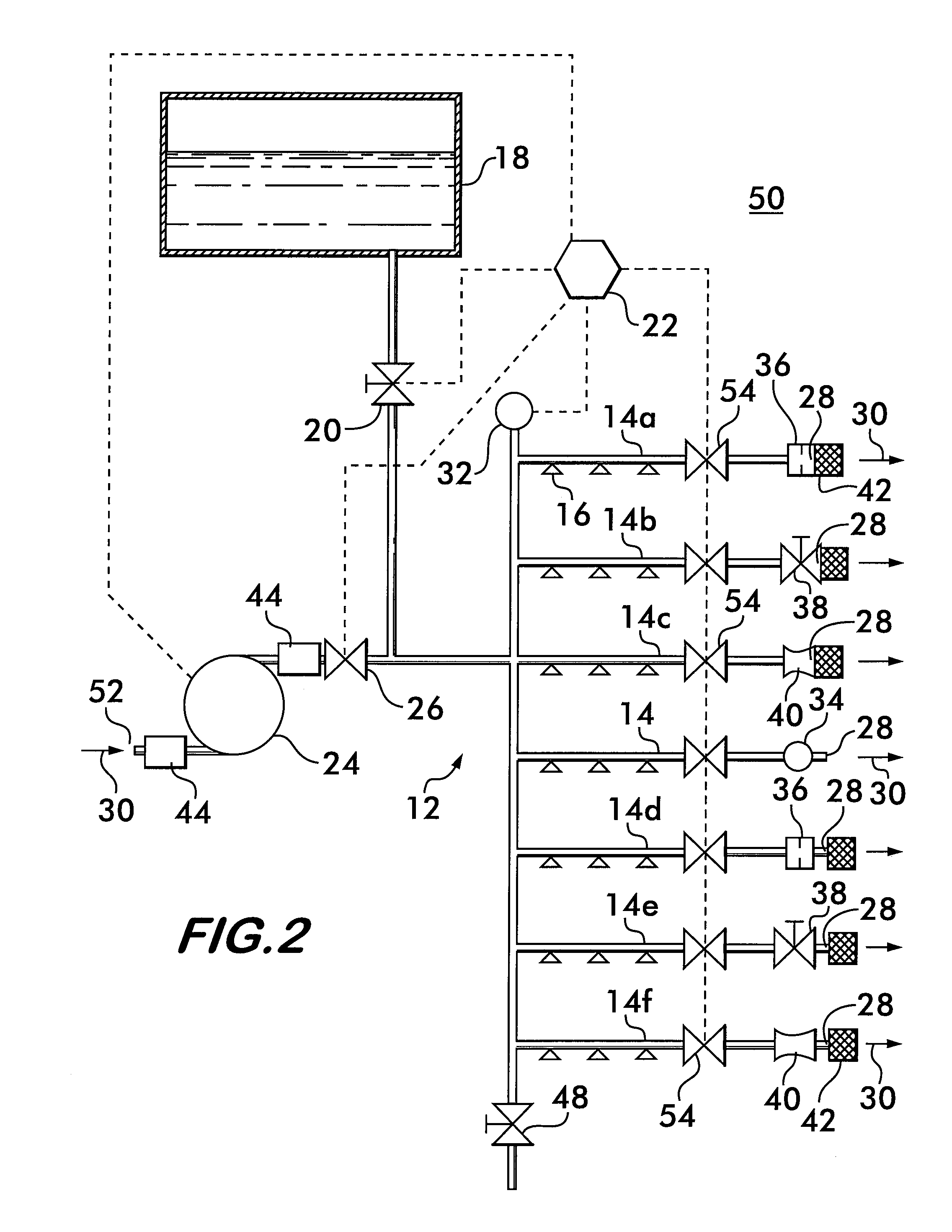
[0021]FIG. 1 shows a schematic diagram of a dry type fire suppression sprinkler system 10 according to the invention. System 10 comprises a piping network 12 formed of a plurality of branches 14 on which are mounted a plurality of sprinkler heads 16. Because it is a dry type system, the piping network, including the branches, is normally substantially devoid of water when not responding to a fire. The branches 14 with their sprinkler heads 16 extend throughout a building, such as a residence, an apartment, an office complex, a warehouse or other structure to be protected. Sprinkler heads 16 may have one of various types of triggering mechanisms which open the heads in response to a fire condition to allow the discharge of water. The well known glass bulb containing a heat sensitive liquid is one example of a triggering mechanism. Other examples include collapsing mechanisms held together by a eutectic solder.
[0022]The piping network 12 connects the sprinkler heads 16 to a source of ...
PUM
| Property | Measurement | Unit |
|---|---|---|
| Flow rate | aaaaa | aaaaa |
Abstract
Description
Claims
Application Information