Sump pump system

a pump system and sump pump technology, applied in the direction of piston pumps, pump control, non-positive displacement fluid engines, etc., can solve the problems of no monitoring of the condition of the back-up battery, no way of increasing the pump discharge rate, and no way to display the expected battery life to the user

Inactive Publication Date: 2007-11-08
GIERKE DANIEL
View PDF9 Cites 105 Cited by
  • Summary
  • Abstract
  • Description
  • Claims
  • Application Information

AI Technical Summary

Benefits of technology

[0013] (a) providing a more reliable and versatile sump pump system;

Problems solved by technology

These prior art systems, however, have presented several drawbacks:
(1) They have no way of increasing the pump discharge rate when a higher discharge is needed to keep pace with liquid flowing into the sump.
(2) There is no monitoring of the condition of the back-up battery or display to the user of the expected battery life.
(3) There is no monitoring of the plumbing and a clog or vapor lock in the discharge pipes will go undetected.
(4) Finally, the prior art systems have no way of notifying the user of a failure within the system.

Method used


Image

  • Sump pump system
  • Sump pump system
  • Sump pump system

Examples


Embodiment Construction

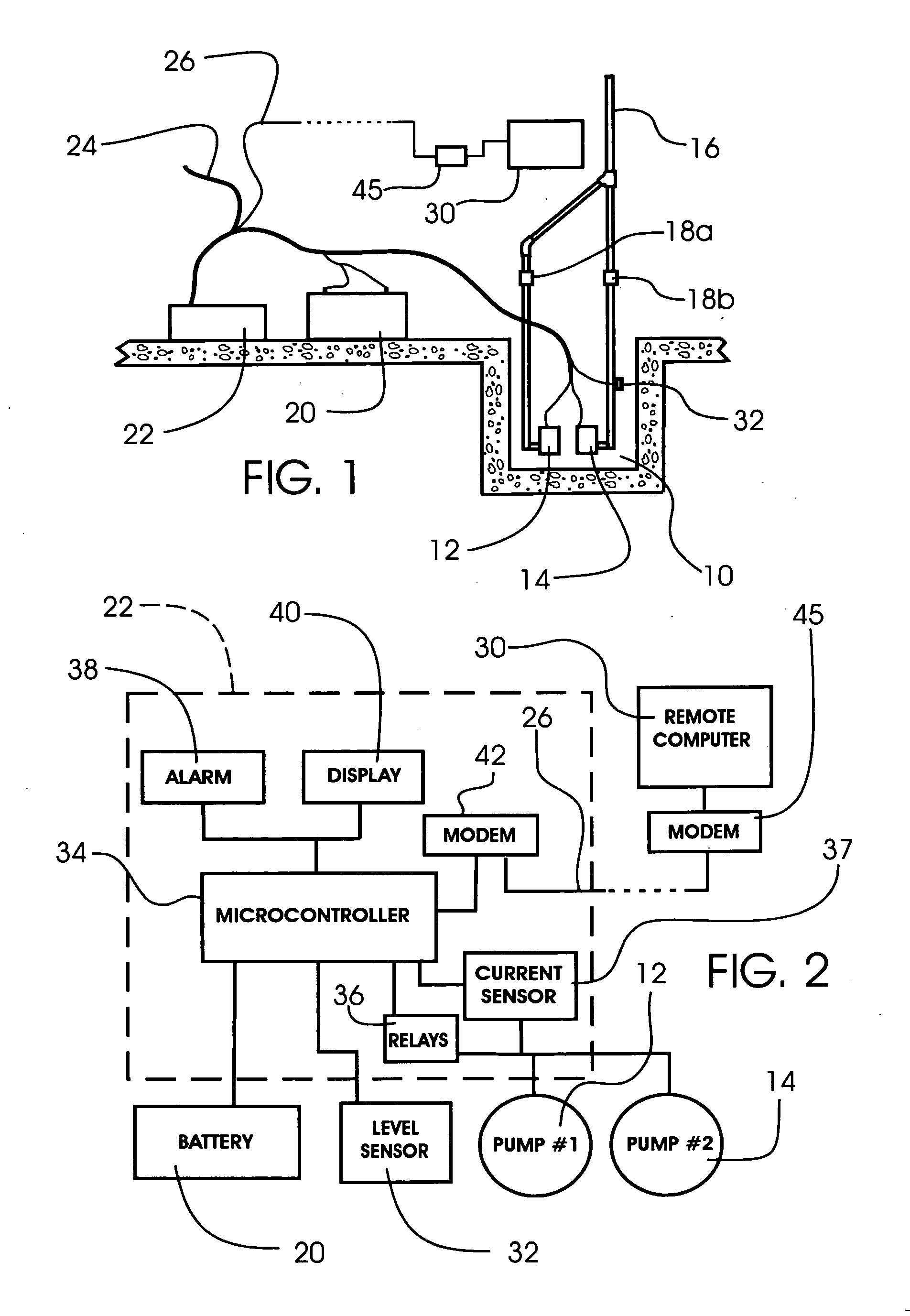
[0032] Turning first to FIG. 1 there is shown a representation of a sump or pit 10 and a pump system in accordance with the present invention for evacuating liquid from the sump. (This pump system may be employed in addition to any other pump system currently in the sump or as the sole pump system in the sump.) Positioned within the sump 10, a first pump 12 and a second pump 14 are shown; but it is to be understood that multiple additional pumps may be employed in the same manner as herein described, and such is considered to be within the scope of this invention.

[0033] The pumps of the present invention are preferably identical electrical motor driven pumps of the usual submersible variety well known in the art for operation within a sump environment, and they are connected therein in the usual manner for pumping liquid from the sump when switched ON. For purposes of this description, the reference herein to a pump being switched ON, or being in an ON condition, shall mean the con...


PUM


Abstract

A programmed microcontroller based sump pump system includes multiple pumps that can be employed with one as a primary pump and one as a back-up, or can be employed in combination to increase the discharge rate. The microcontroller monitors the back-up battery condition, and computes and displays the battery life; monitors the system for clogs or vapor locks in the discharge piping; switches to an emergency periodic pumping mode of operation, when needed; and notifies the user by phone or e-mail of a system malfunction.

Description

CROSS REFERENCE TO RELATED APPLICATIONS [0001] Not Applicable STATEMENT REGARDING FEDERALLY SPONSORED RESEARCH OR DEVELOPMENT [0002] Not Applicable BACKGROUND OF THE INVENTION [0003] 1. Field of the Invention [0004] The present invention relates generally to pumps used to remove water or other liquid from a sump or pit. More particularly, this invention relates to apparatus for monitoring and improving the reliability of a sump pump system, and in a further feature, to direct user notification of malfunctions or failures in the sump pump system. [0005] 2. Description of the Prior Art [0006] It is well known in the prior art to provide a pump within a pit or sump that operates from an electrical power line power source. Moreover, to improve the reliability of such prior art pump system, it is also known to add a secondary back-up pump which is powered by a back-up battery power source. Consequently, when there is a power failure that causes the power to the primary pump to be interru...

Claims


Application Information

Patent Timeline
Patent Type & Authority Applications(United States)
IPC IPC(8): F04B41/06F04B49/06
CPCF04D13/068F04D15/029
Inventor GIERKE, DANIEL
Owner GIERKE DANIEL
Why Eureka
Try Eureka