Image processing apparatus

a technology of image processing and apparatus, which is applied in the field of image processing apparatus, can solve the problems of inability of the user to see the rear area of the vehicle, the inability of the interior rearview mirror to be used and the inability of the driver to see the surrounding area behind the vehicl

Active Publication Date: 2017-02-02
FUJITSU GENERAL LTD
View PDF0 Cites 8 Cited by
  • Summary
  • Abstract
  • Description
  • Claims
  • Application Information

AI Technical Summary

Problems solved by technology

However, even if using the interior rearview mirror, there is a case where it is difficult for the driver to see the surrounding area behind the vehicle, for example, because driver's view is blocked by an occupant or luggage in a rear area of the cabin of the vehicle.
Moreover, in a case of a truck having a container and the like, there is a case where the interior rearview mirror cannot be used to see the surrounding area behind the vehicle.
The foregoing image display system does not display an image showing the cabin of the vehicle so that it is not possible for the user to see the rear area of the cabin of the vehicle.
Therefore, it is impossible to use only a partial region of the display screen of the display apparatus as a mirror.
Thus, for example, it is difficult for the user to see both of the surrounding area behind the vehicle and the rear area of the cabin of the vehicle at the same time.

Method used


Image

  • Image processing apparatus
  • Image processing apparatus
  • Image processing apparatus

Examples


first embodiment

1. First Embodiment

[0035]

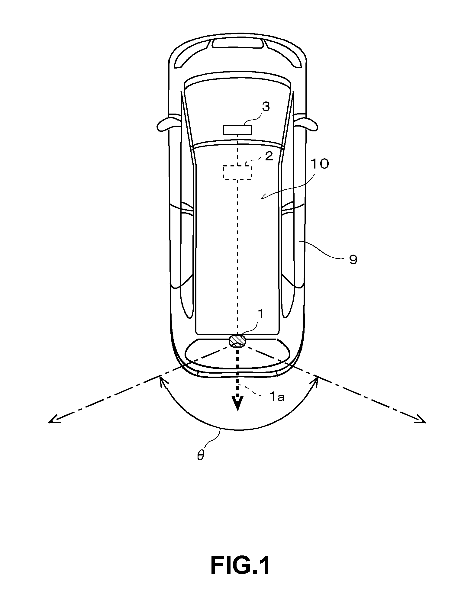
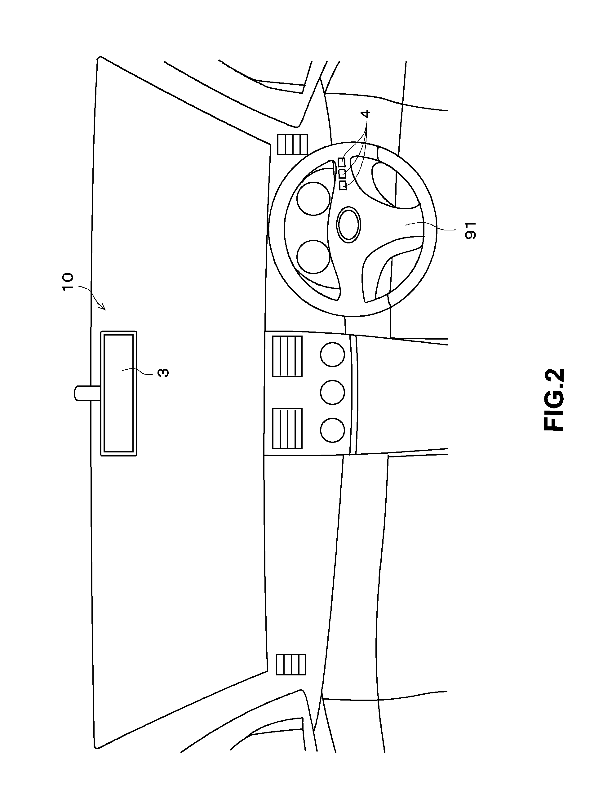
[0036]FIG. 1 illustrates an outline of an image display system 10. As shown in FIG. 1, the image display system 10 is mounted on a vehicle (a car in this embodiment) 9. The image display system 10 includes a camera 1 that captures an image of surroundings of the vehicle 9, an image processing apparatus 2 that processes the image and a display apparatus 3 that is provided in a cabin of the vehicle 9. The image display system 10 captures an image of a subject in the surroundings of the vehicle 9, using the camera 1, and has a function of displaying a display image showing the subject on the display apparatus 3 in the cabin of the vehicle.

[0037]The camera 1 includes a lens and an image sensor, and electronically captures the captured image including the image of the subject in the surroundings of the vehicle 9. The camera 1 is mounted in an upper portion of a rear end of the vehicle 9, having an optical axis la directed to rearward along a front-back direction ...

second embodiment

2. Second Embodiment

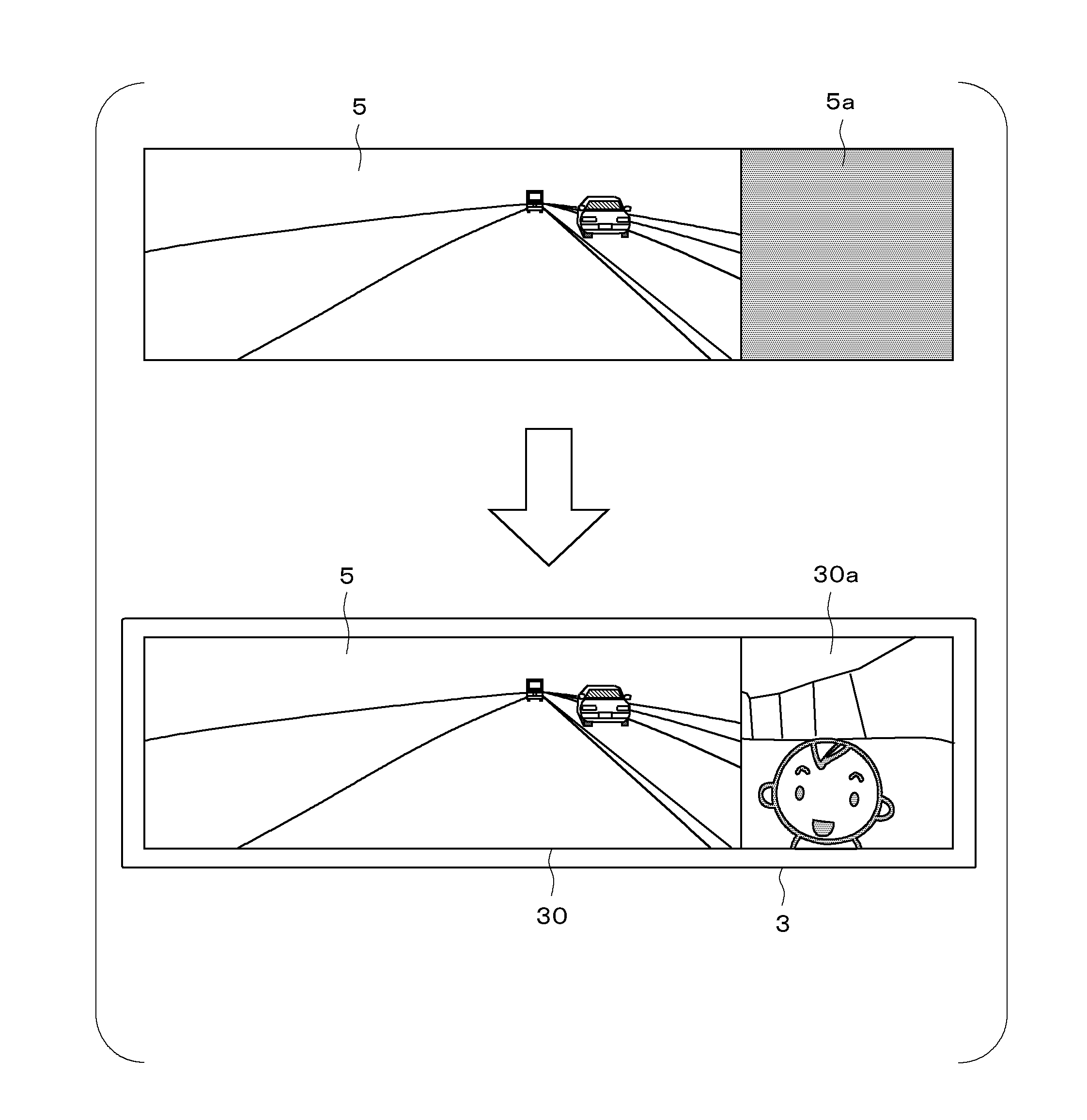
[0080]Next, a second embodiment will be described. A configuration and a process of an image display system 10 in the second embodiment are substantially the same as the configuration and the process of the image display system 10 in the first embodiment. Therefore, a difference from the image display system 10 in the first embodiment will be mainly described below. In the first embodiment, the region of the display image 5 to be the black image is predetermined. On the other hand, in the second embodiment, a user can specify a region of a display image 5 to be a black image.

[0081]FIG. 11 illustrates a block diagram showing the configuration of the image display system 10 in the second embodiment. In the second embodiment, a display apparatus 3 includes a touch panel 34 that receives a touch operation made by the user, on a display screen 30. Therefore, the user can make the touch operation with the display screen 30 (the touch panel 34) of the display apparatus ...

third embodiment

3. Third Embodiment

[0093]Next, a third embodiment will be described. A configuration and a process of an image display system 10 in the third embodiment are substantially the same as the configuration and the process of the image display system 10 in the first embodiment. Therefore, a difference from the image display system 10 in the first embodiment will be mainly described below. In the first embodiment, in the case where the user presses one of the plurality of operation buttons 4, a partial region of the display screen 30 functions as the mirror on the display apparatus 3. On the other hand, in the third embodiment, in a case where a sound occurs in a cabin of a vehicle 9, a partial region of a display screen 30 functions as a mirror on the display apparatus 3.

[0094]FIG. 14 illustrates a block diagram showing the configuration of the image display system 10 in the third embodiment. The image display system 10 in the third embodiment includes a microphone 6 for receiving the sou...


PUM


Abstract

A display screen of a display apparatus of an image display system includes a one-way mirror on a front side of the display screen. In an image processing apparatus, an image signal input obtains a captured image signal representing a captured image captured by a camera that captures an image of surroundings of the vehicle; an image generator that generates the display image from the captured image signal; an image output that outputs the display image to the display apparatus to cause the display image to be displayed on the display screen of the display apparatus; and a processor that controls the image generator to cause a partial region of the display image to be a black image so that a portion of the display screen at which the black image is displayed functions as a mirror.

Description

BACKGROUND OF THE INVENTION[0001]Field of the Invention[0002]The invention relates to a technology for displaying an image showing surroundings of a vehicle.[0003]Description of the Background Art[0004]Generally, a driver of a vehicle, such as a car, sees a surrounding area behind the vehicle by looking at an interior rearview mirror provided in a cabin of the vehicle. However, even if using the interior rearview mirror, there is a case where it is difficult for the driver to see the surrounding area behind the vehicle, for example, because driver's view is blocked by an occupant or luggage in a rear area of the cabin of the vehicle. Moreover, in a case of a truck having a container and the like, there is a case where the interior rearview mirror cannot be used to see the surrounding area behind the vehicle.[0005]Therefore, an image display system has been recently proposed that captures an image of a subject in a surrounding area behind a vehicle, using a camera, and that displays ...

Claims


Application Information

Patent Timeline
Patent Type & Authority Applications(United States)
IPC IPC(8): H04N5/272B60R1/04B60R1/12H04N7/18H04N5/232
CPCH04N5/272H04N7/183H04N5/23293H04N7/188B60R2300/207B60R1/12B60R1/04B60R2001/1253H04N5/23216B60R1/00B60R2300/70B60R2300/8013H04N23/63H04N23/635
Inventor SAWADA, YASUYOSHI
Owner FUJITSU GENERAL LTD
Why Eureka
Try Eureka