
Electromagnetically driven automotive sliding door

a technology of electric motor and sliding door, which is applied in the direction of doors, wing accessories, transportation and packaging, etc., can solve the problems of increasing weight, manufacturing complexity, increasing cost, etc., and achieve the effect of minimal dynamic friction

Inactive Publication Date: 2017-02-23
MAGNA CLOSURES INC
View PDF16 Cites 2 Cited by
  • Summary
  • Abstract
  • Description
  • Claims
  • Application Information

AI Technical Summary

Benefits of technology

This patent describes a sliding door system for vehicles that uses magnetic force to move the door between open and closed positions. The system includes at least one permanent magnet fixed to the door panel and at least one pole permanent magnet mounted next to the door panel. These magnets are magnetically coupled, allowing the door to move smoothly without excessive friction. The magnets are positioned at the lower edge of the door panel and the pole opposite the second magnet, and they have the same polarity to minimize friction with the vehicle's door track. This technology allows for easy and comfortable sliding of the door, making it a more convenient and user-friendly option for vehicle users.

Problems solved by technology

Although current electromechanical drive devices generally perform their intended function as initially installed, components brought into dynamic frictional engagement with one another are prone to wear over time, thereby resulting in noise, and typically require servicing.
Further yet, mechanical components in such systems typically result in an increased number of components, thereby increasing weight and manufacturing complexity, which in turn typically results in increased cost.

Method used


Image

  • Electromagnetically driven automotive sliding door
  • Electromagnetically driven automotive sliding door
  • Electromagnetically driven automotive sliding door

Examples


Embodiment Construction

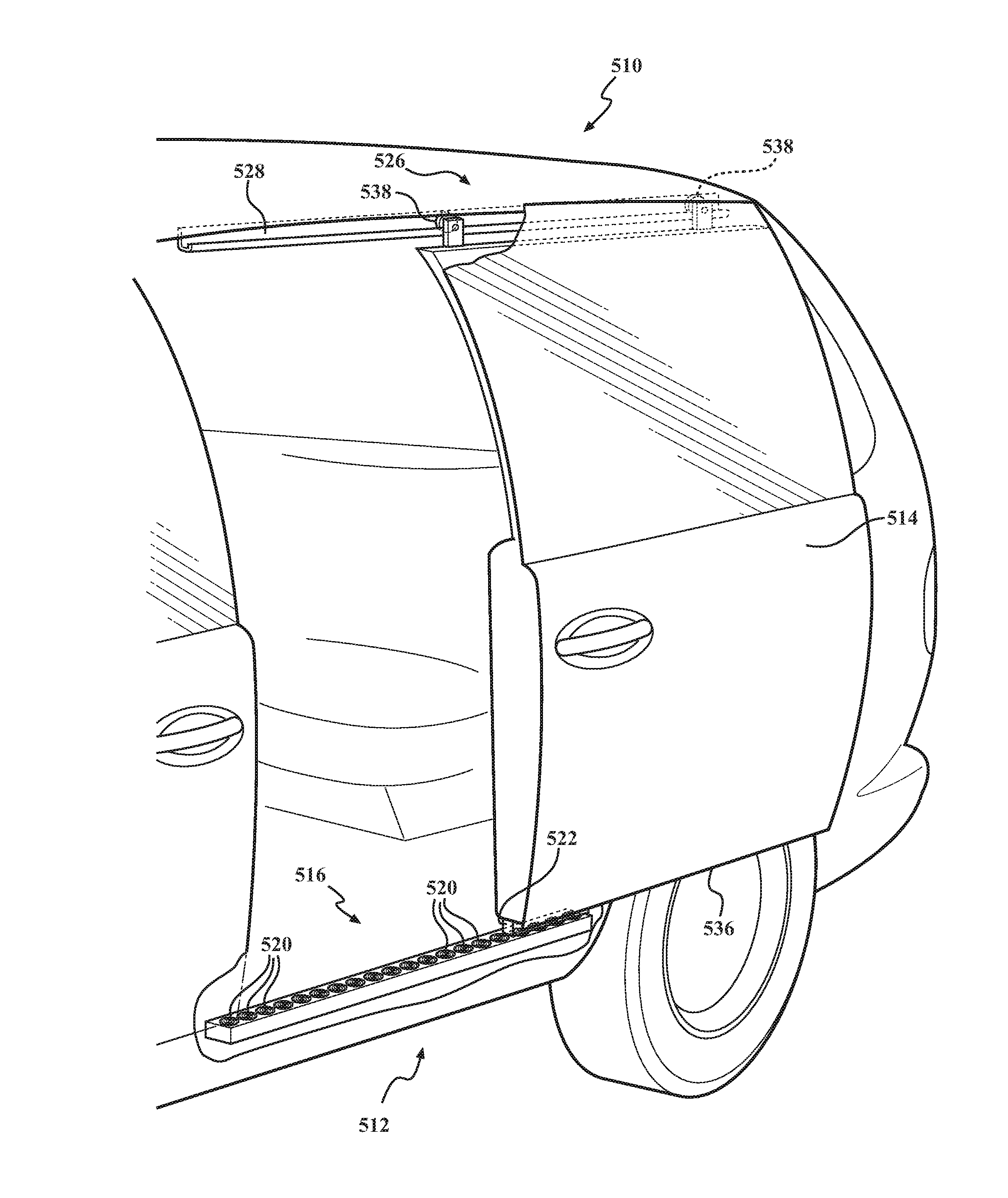
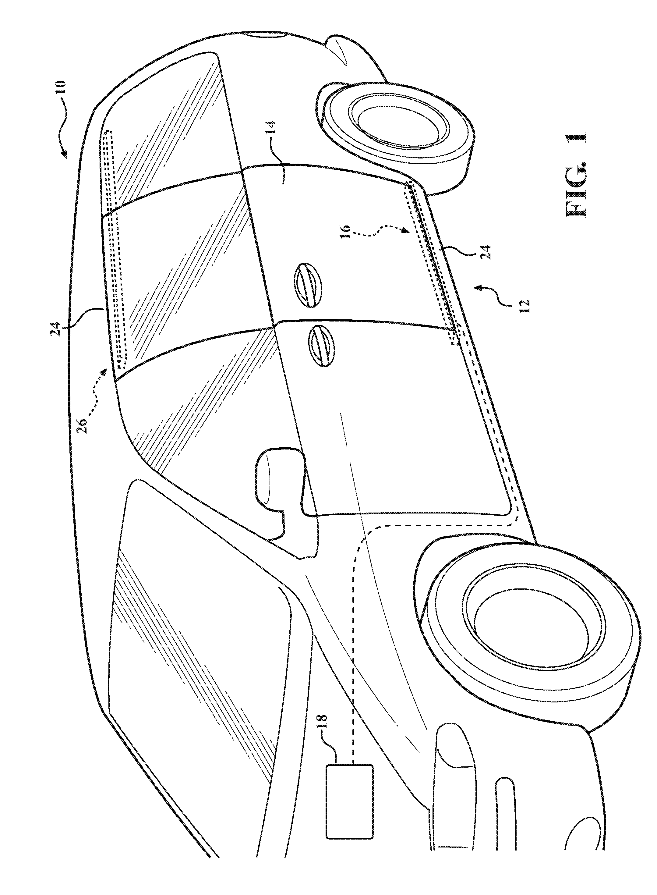
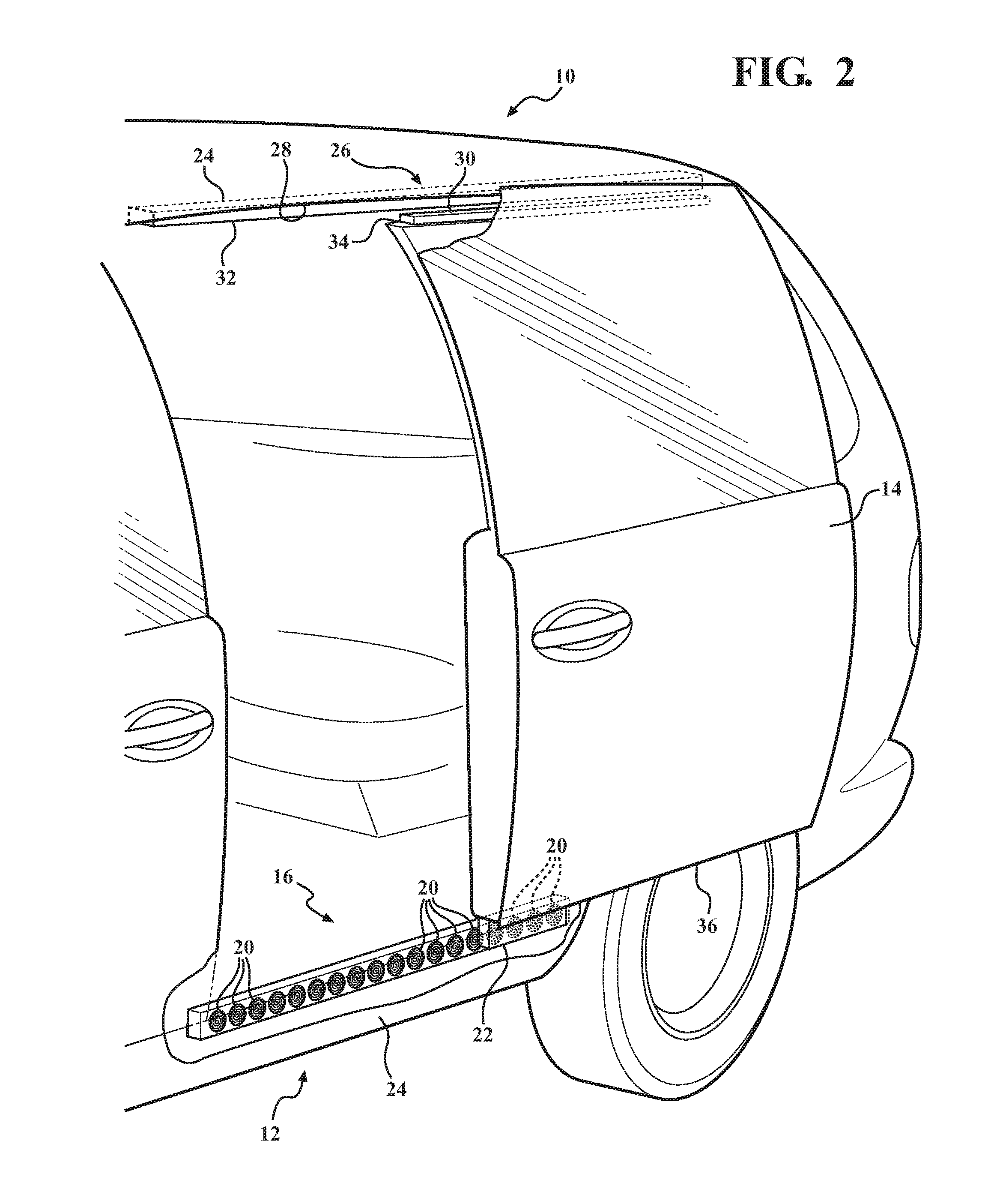
[0021]For purposes of descriptive clarity, the present disclosure is described herein in the context of one or more specific vehicular applications, namely sliding door systems or other sliding vehicle panels (sliding herein includes any linearly translatable door / panel, such as via direct sliding, rollers, wheels, skids, or otherwise). Upon reading the following detailed description in conjunction with the appended drawings and claims, it will be clear that the inventive concepts of the present disclosure can be applied to other systems and applications including linearly translatable, sliding members. The electromagnetically coupled, relatively slidable features combine to extend the useful life of the system components, reduce dynamic friction between system components, reduce the system weight, and further provide a perceived quality enhancement by reducing noise and wear between the moveable components.

[0022]The terminology used herein is for the purpose of describing particula...


PUM


Abstract

An electromagnetic system for a powered vehicle door for driving the door forward and / or backward between open and closed positions is provided. The electromagnetically driven sliding door includes a door panel with at least one permanent first magnet fixed to the door panel. A plurality of electromagnetic coils are operably mounted adjacent the door panel. The electromagnetic coils are configured in electrical communication with a source of electric current of alternating first and second polarities. The electromagnetic coils are energizable via the electric current to attract the at least one first permanent magnet in response to the first polarity electric current and to repel the at least one first permanent magnet in response to the second polarity electric current to drive the door panel between open and closed positions. Permanent pole magnets can be incorporated to facilitate supporting the door within a door track of the door.

Description

CROSS-REFERENCE TO RELATED APPLICATION[0001]This application claims the benefit of U.S. Provisional Application Ser. No. 62 / 207,743, filed Aug. 20, 2015, which is incorporated herein by reference in its entirety.FIELD OF THE INVENTION[0002]The present disclosure relates generally to sliding doors for automotive vehicles, and more particularly, to powered sliding doors for automotive vehicles.BACKGROUND OF THE INVENTION[0003]This section provides background information which is not necessarily prior art to the inventive concepts associated with the present disclosure.[0004]Vehicles, such as passenger vehicles, are generally equipped with numerous moveable closure members or panels for providing openings and access within and through various defined portions of the vehicle. To enhance operator convenience, many vehicles are now equipped with power-operated closure systems to automatically control movement of all types of closure panels including, without limitation, sliding doors, sun...

Claims


Application Information

Patent Timeline
IPC IPC(8): E05F15/60E05D15/06B60J5/04E06B3/46
CPCE05F15/60E06B3/4636E05Y2900/531B60J5/047E05Y2201/462E05D15/063B60J5/06
Inventor MITCHELL, J.R. SCOTT
Owner MAGNA CLOSURES INC
Learn More