
Lubrication system and method of making the same

a technology of lubricating system and lubricating pump, which is applied in the direction of lubricating pump, lubricating element, safety/regulatory device, etc., can solve the problems of inoperable equipment, need for expensive environmental remediation of the ground, and overheating of equipmen

Inactive Publication Date: 2017-02-23
CANSERV LLC
View PDF3 Cites 8 Cited by
  • Summary
  • Abstract
  • Description
  • Claims
  • Application Information

AI Technical Summary

Benefits of technology

This patent is about a lubrication system that provides lubrication to equipment. It includes a container for lubrication, a pump to push the lubrication to the equipment, a conduit to deliver the lubrication, and a control system to manage the amount of lubrication provided. The system can also have a sensor to measure how the equipment is doing and adjust the amount of lubrication accordingly. The patent also describes how to use the lubrication system to lubricate equipment. In simple terms, this is a way to make sure machines are always getting the right amount of lubrication.

Problems solved by technology

Equipment requiring lubrication has to be lubricated a specific amount at specific locations or problems can occur.
If the equipment is lubricated to little, the equipment can overheat and become inoperable.
If the equipment gets too much lubrication, an environmental problem can arise due to excessive amounts of lubrication falling to the ground causing the need for expensive environmental remediation of the ground.

Method used


Image

  • Lubrication system and method of making the same
  • Lubrication system and method of making the same
  • Lubrication system and method of making the same

Examples


Embodiment Construction

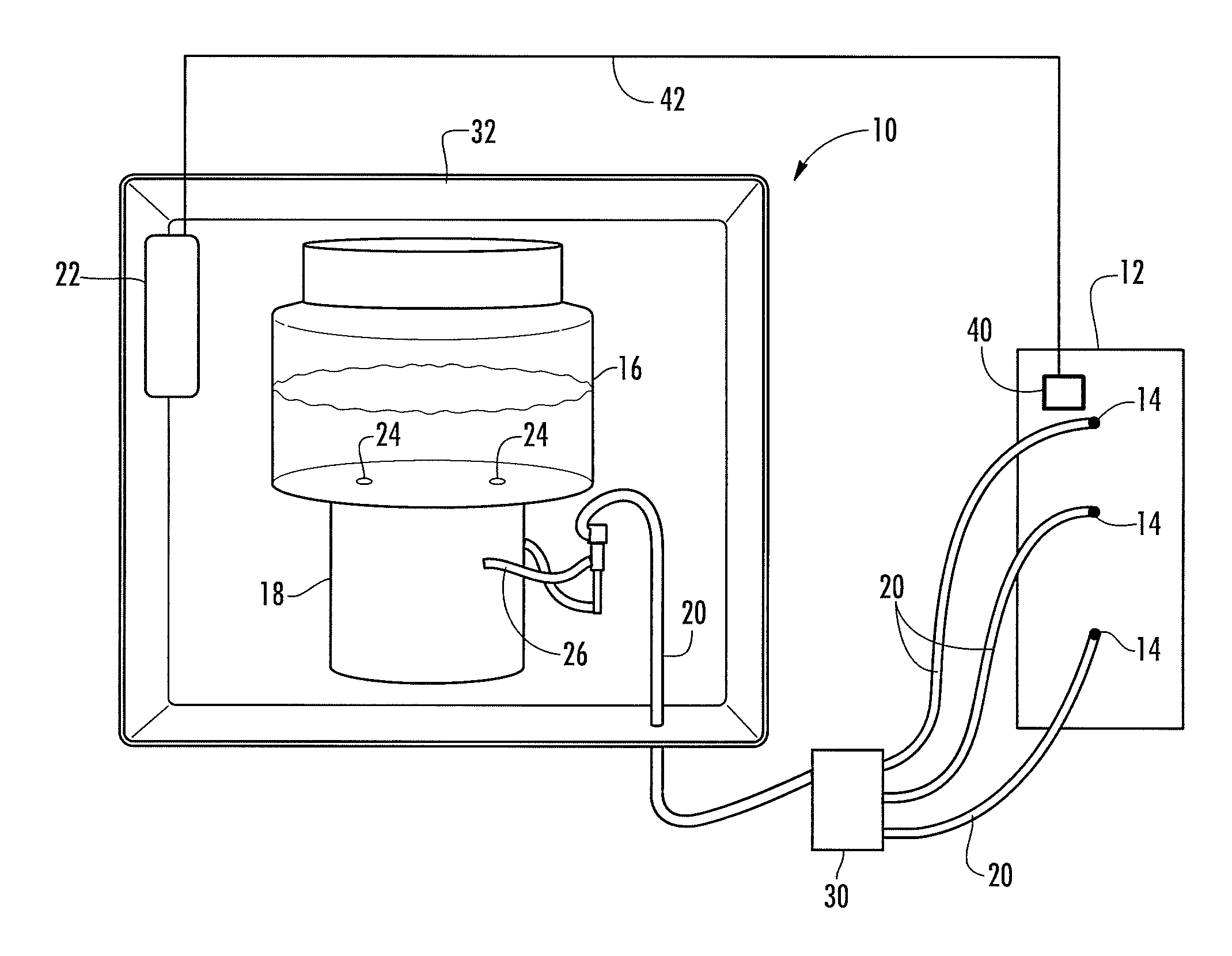
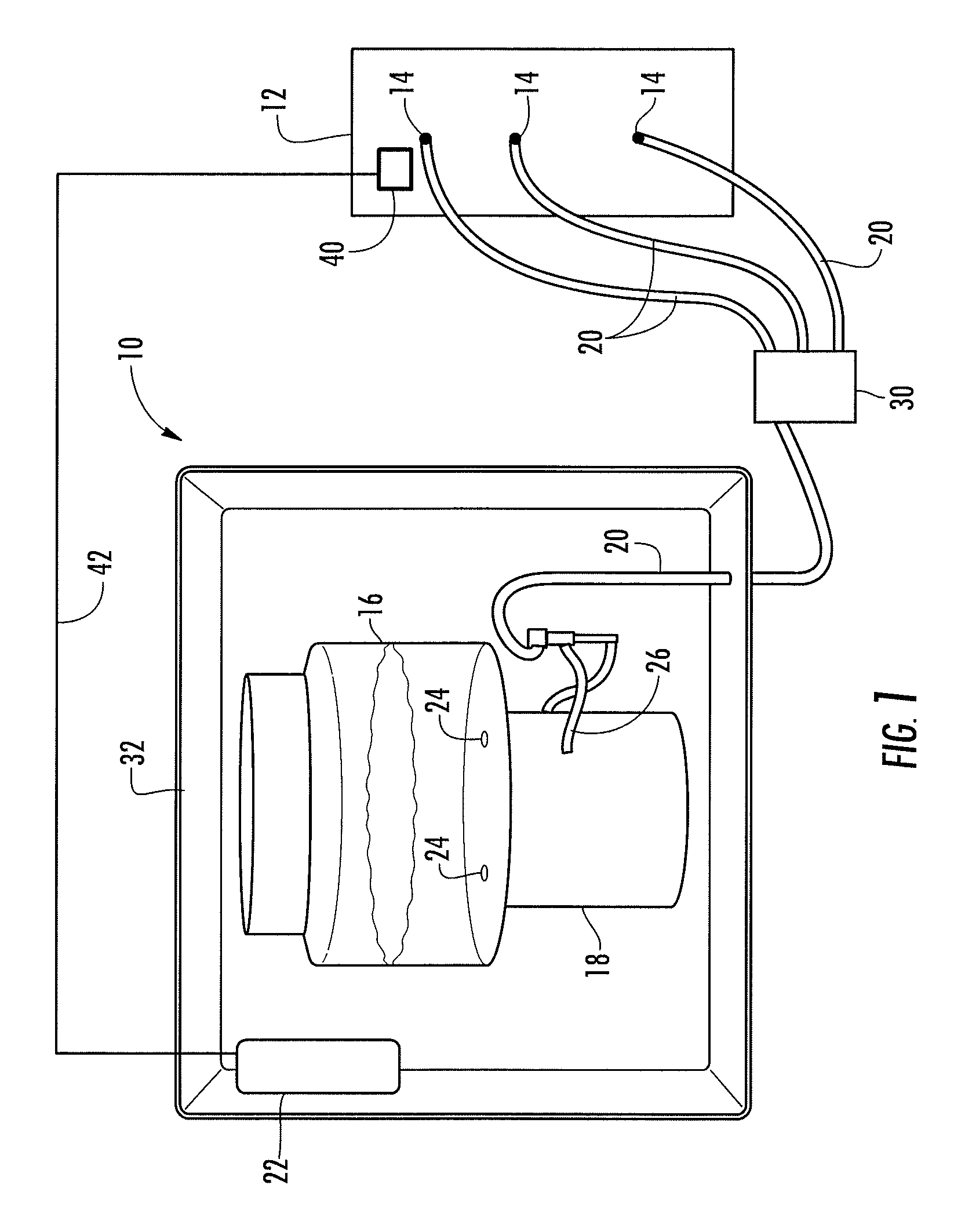
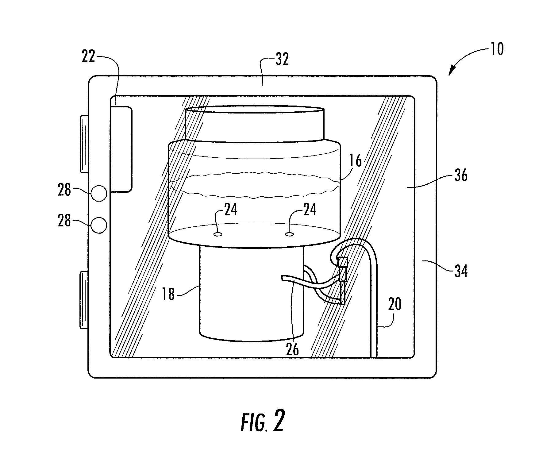
[0011]The present disclosure relates to a lubrication system 10 for use with equipment 12 to provide a preselected lubricant to lubrication points 14 of the equipment 12. It should be understood and appreciated that the equipment 12 can be any type of equipment known in the art requiring grease injected therein to operate, or operate more efficiently. Furthermore, the lubrication points 14 can be any type of input for equipment 12 whereby lubrication may be provided thereto. The equipment 12 is depicted as a box in the figures. The equipment 12 has lubrication points 14 whereby lubricant can be injected into predetermined locations of the equipment 12.

[0012]Referring now to FIG. 1, shown therein is the lubrication system 10 constructed in accordance with one embodiment of the present disclosure. In this embodiment, the lubrication system 10 includes a lubrication container 16 for housing the desired lubricant, a lubrication pump 18 to force the lubricant into the equipment 12 via th...


PUM


Abstract

A lubrication system for providing lubrication to equipment is disclosed herein. Generally, the lubrication system includes a lubrication supply container, a lubrication pump, a conduit for providing the lubricant to the oilfield pump, and a control system for setting the operating parameters of the lubrication system. The lubrication system can also include a sensing device for measuring various operational aspects of the equipment and adjusting the amount of lubrication responsive to data measured by the sensing device.

Description

CROSS-REFERENCE TO RELATED APPLICATIONS[0001]The present application is a conversion of U.S. Provisional Application having U.S. Ser. No. 62 / 205,944, filed Aug. 17, 2015, which claims the benefit under 35 U.S.C. 119(e). The disclosure of which is hereby expressly incorporated herein by reference.STATEMENT REGARDING FEDERALLY SPONSORED RESEARCH OR DEVELOPMENT[0002]Not Applicable.BACKGROUND OF THE DISCLOSURE[0003]1. Field of the Invention[0004]This disclosure relates to a lubrication system that can be used in conjunction with equipment requiring lubrication. The lubrication system facilitates the delivery of a lubricant to lubrication points located on the equipment.[0005]2. Description of the Related Art[0006]Equipment requiring lubrication has to be lubricated a specific amount at specific locations or problems can occur. If the equipment is lubricated to little, the equipment can overheat and become inoperable. If the equipment gets too much lubrication, an environmental problem c...

Claims


Application Information

Patent Timeline
Patent Type & Authority Applications(United States)
IPC IPC(8): F16N29/02
CPCF16N29/02F16N2270/70F16N2260/00F16N2210/16F16N13/00F16N19/00F16N19/006F16N2270/32
Inventor BUSCH, CHARLES C.COPLEY, DALLASBRADSHAW, JEFF
Owner CANSERV LLC
Learn More