Motion-Activated Venting System

a technology of motion and venting, applied in the field of venting systems, can solve problems such as reducing ventilation, and achieve the effects of enhancing ventilation, enhancing ventilation, and enhancing ventilation

Active Publication Date: 2017-03-09
NIKE INC
View PDF35 Cites 33 Cited by
  • Summary
  • Abstract
  • Description
  • Claims
  • Application Information

AI Technical Summary

Benefits of technology

[0006]At a high level, aspects described herein relate to motion-activated venting systems that can be incorporated into articles of apparel. The motion-activated venting systems described herein function as a valve; they are adapted to open when the wearer is active and to close when the wearer is inactive. As a result, the motion-activated venting systems described herein dynamically and automatically enhance ventilation when the wearer is physically active. Additionally, the motion-activated venting systems decrease ventilation when the wearer is sedentary, allowing the wearer to retain heat. Further, specific regions of the body produce and attract more heat than others. Advantageously, the motion-activated venting systems described herein can be incorporated into an article of apparel at any desirable location. For example, the upper back attracts and produces an abundance of heat. Incorporating a motion-activated venting system at the upper back portion of the apparel item provides the wearer increased comfort by enhancing ventilation at the heat producing region while the wearer is active. Further, multiple combinations of the various aspects of the motion-activated venting systems described herein can also be incorporated into and placed at various locations of an article of apparel. As a result, the motion-activated venting system can be employed to achieve desired ventilation properties based on the intended use of the article of apparel and the preferences of the wearer.
[0008]In an aspect herein, the pleats described may have at least a first fold having a first folded edge and a ventilation region. The ventilation region may comprise a plurality of apertures and / or may be in the form of a mesh material. In other aspects, a pleat may additionally have a second fold or a second portion having a second folded edge. When the pleat is in a first, inactive state, the plurality of apertures are covered or substantially covered by the first fold and / or the second fold due to the folded configuration of the pleat. This allows the wearer to retain body heat before physical activity has begun or after physical activity has ceased. Conversely, when the pleat is in a second, active state, the plurality of apertures is exposed. The edges and folds of the various pleats automatically move away from one another when the wearer is active due to airflow created by the motion of the wearer and / or the tension or stretch forces created by the body of the wearer and the wearer's movement. Consequently, the plurality of apertures of the ventilation region is exposed. Additionally, the degree to which the edges and folds of the pleats move away from one another corresponds to the amount of airflow and tension / stretch forces. As a result, a greater degree of ventilation is provided to the wearer by virtue of exposure of the plurality of apertures, which allow airflow to cool the body of the wearer and / or for the body heat of the wearer to dissipate.
[0009]In one aspect, a pleat may be configured as a box pleat or an inverted box pleat. The box pleat may comprise a first fold and an opposite second fold. As used herein, the term “opposite” may refer to a feature that is located adjacent to, but separate from, another feature, or to a feature that is facing another feature. Continuing, the first fold terminates in a first folded edge and the second fold terminates in a second folded edge. A ventilation region is interposed between the first fold and the second fold. Further, the ventilation region has a plurality of apertures and / or a mesh material. The plurality of apertures are covered or substantially covered by the first fold and the second fold when the motion-activated venting system is in a first, inactive state. As used herein, the term “cover” may indicate that a feature occludes, lies on or over, or obstructs the visibility of another feature. This allows the wearer to retain body heat before physical activity has begun or after physical activity has ceased. When the box pleat is in the second, active state, the first fold and the second fold move away from one another, exposing the plurality of apertures and providing enhanced ventilation.
[0010]In additional aspects, the motion-activated venting system may take the form of an accordion pleat. In this aspect, there may be a plurality of folds having creases. Disposed between adjacent creases, there may be a ventilation region with a plurality of apertures and / or a mesh material. Because of the accordion structure, when the accordion pleat is in a first, inactive state, the apertures are unexposed. Conversely, when the accordion pleat is in a second, active state, the accordion pleat expands, exposing the plurality of apertures and thereby providing enhanced ventilation.
[0011]The motion-activated venting system may also be embodied in various other forms. For example, the motion-activated venting system may include a knife pleat or a bias pleat. In these configurations, the pleat may have a first folded edge and a ventilation region, the ventilation region having a plurality of apertures. When the pleat is in a first, inactive state, the first edge covers the ventilation region, thereby allowing the wearer to retain body heat. When the pleat is in a second, active state, the plurality of apertures is exposed, thereby providing enhanced ventilation. In other forms, instead of having a plurality of apertures, a mesh material may be used. Thus, when the pleat is in a first, inactive state, the first edge covers the mesh material, thereby allowing the wearer to retain body heat. And when the pleat is in a second, active state, the mesh material is exposed, thereby providing enhanced ventilation.

Problems solved by technology

Additionally, the motion-activated venting systems decrease ventilation when the wearer is sedentary, allowing the wearer to retain heat.

Method used


Image

  • Motion-Activated Venting System
  • Motion-Activated Venting System
  • Motion-Activated Venting System

Examples


Embodiment Construction

[0051]The subject matter of the present invention is described with specificity herein to meet statutory requirements. However, the description itself is not intended to limit the scope of this patent. Rather, the inventors have contemplated that the claimed subject matter might also be embodied in other ways, to include different steps or combinations of steps similar to the ones described in this document, in conjunction with other present or future technologies. Moreover, although the terms “step” and / or “block” might be used herein to connote different elements of methods employed, the terms should not be interpreted as implying any particular order among or between various steps herein disclosed unless and except when the order of individual steps is explicitly stated.

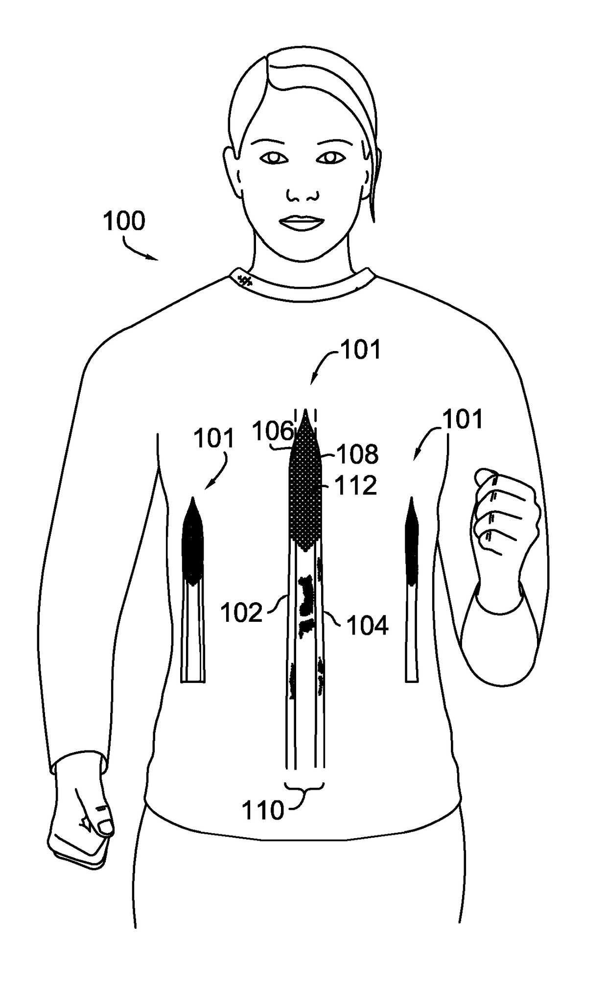
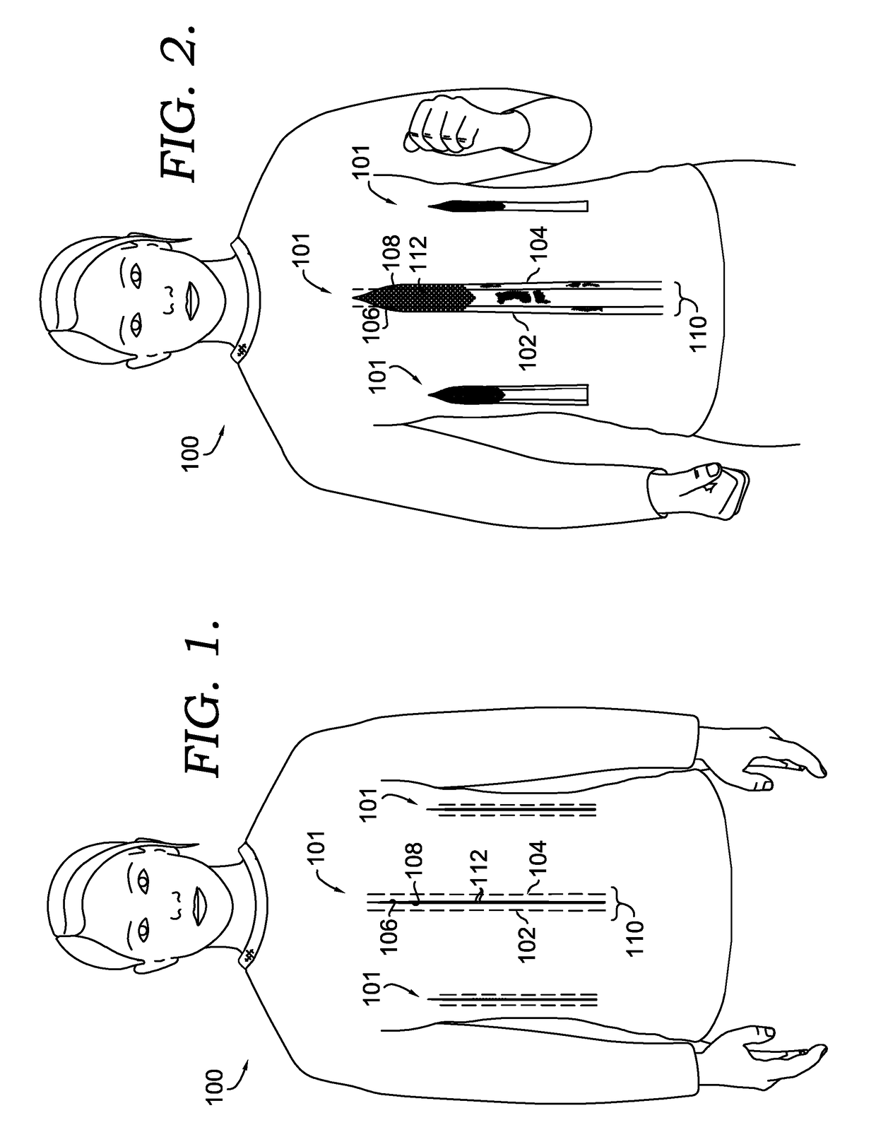
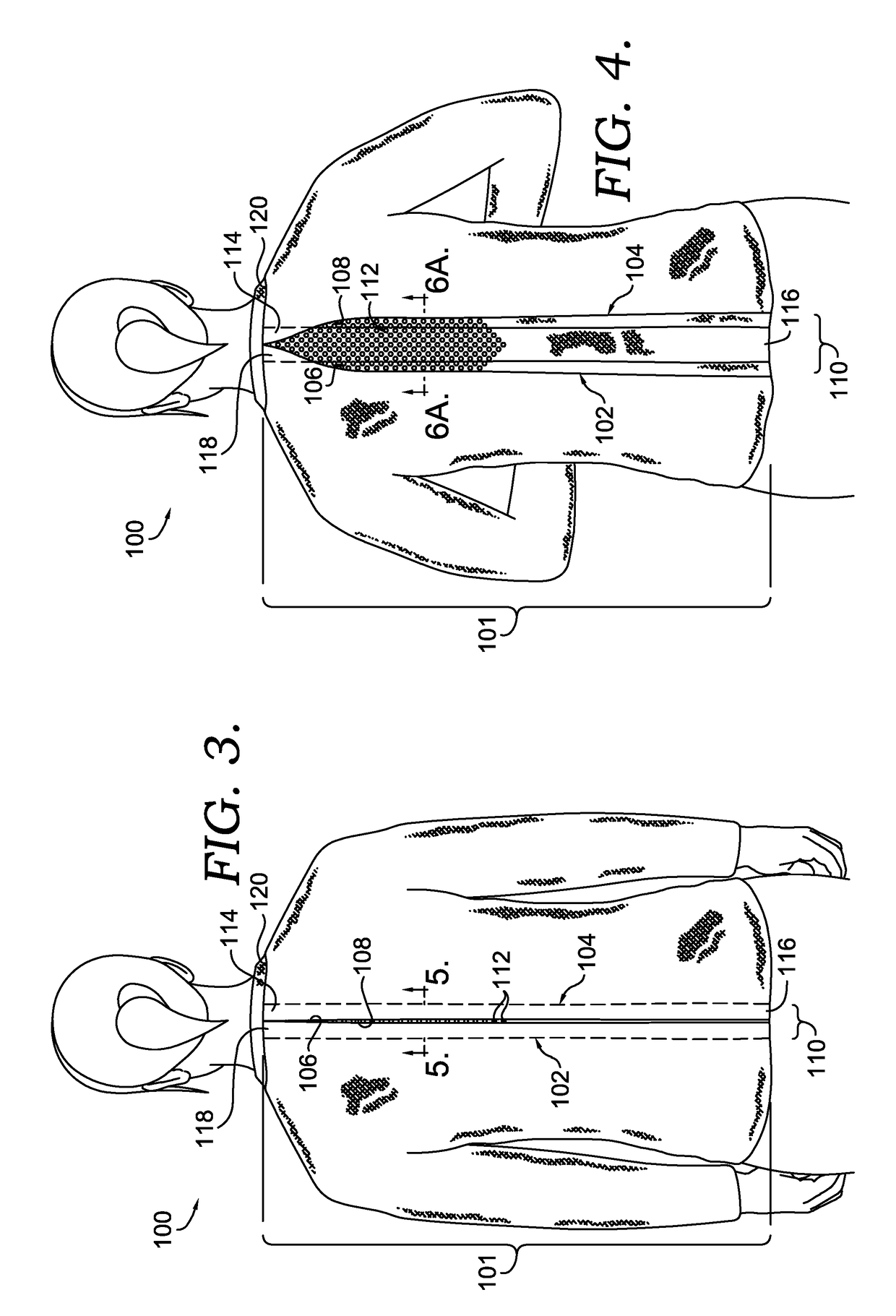
[0052]Aspects herein relate to a motion-activated venting system for incorporation into an article of apparel. In exemplary aspects, the motion-activated venting system may have at least one fold with an edge or a...


PUM


Abstract

A motion-activated venting system for incorporation into an article of apparel is described herein. The motion-activated venting system may comprise a variety of pleats having one or more folded edges and a ventilation region having a plurality of apertures. In a first state, the one or more folded edges overlie the ventilation region such that the plurality of apertures is covered. In a second state, the one or more folded edges are remote from the ventilation region such that the plurality of apertures is exposed. Further, in an intermediate state, the motion-activated venting system is partially open, thereby exposing a portion of the plurality of apertures.

Description

[0001]This application claims the benefit of U.S. Provisional Application No. 62 / 216,147, filed Sep. 9, 2015, and entitled “Motion-activated Venting System.” The entirety of the aforementioned application is incorporated by reference herein.TECHNICAL FIELD[0002]The present disclosure relates to a venting system for incorporation into articles of apparel. More specifically, the present disclosure relates to a motion-activated venting system that provides enhanced ventilation to a wearer of an article of apparel when the wearer is active.BACKGROUND[0003]Traditionally, apparel has failed to provide dynamic ventilation. Particularly for those engaged in exercise or other physical activity, regulating body temperature is problematic. For example, a shirt may feel appropriate for the ambient temperature before a wearer begins a run. However, once a person has begun running, they may find the same shirt is causing them discomfort because their body temperature has increased. Traditionally,...

Claims


Application Information

Patent Timeline
Patent Type & Authority Applications(United States)
IPC IPC(8): A41D13/002A41D1/02A41D1/04B26D3/12A41D27/10A41D27/28A41D1/08A41H33/00A41B1/00A41D3/02
CPCA41D13/002A41B1/00A41D1/02A41D1/04A41D3/02A41D2400/20A41D27/285A41D1/08A41H33/00B26D3/12A41D27/10A41D27/28A41D2300/24A41D2600/10A41D31/145
Inventor NORDSTROM, MATTHEW D.
Owner NIKE INC
Why Eureka
Try Eureka