Device for cleaning plant pots
a plant pot and cleaning technology, applied in the direction of cleaning process and apparatus, cleaning using liquids, brushes, etc., can solve the problems of poor cleaning effect, high labor intensity, and low capacity of plant pots, and achieve the effect of reliably cleaning
- Summary
- Abstract
- Description
- Claims
- Application Information
AI Technical Summary
Benefits of technology
Problems solved by technology
Method used
Image
Examples
Embodiment Construction
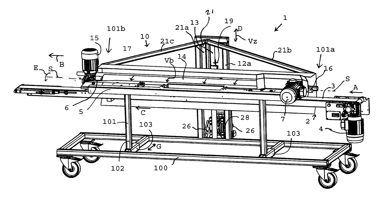
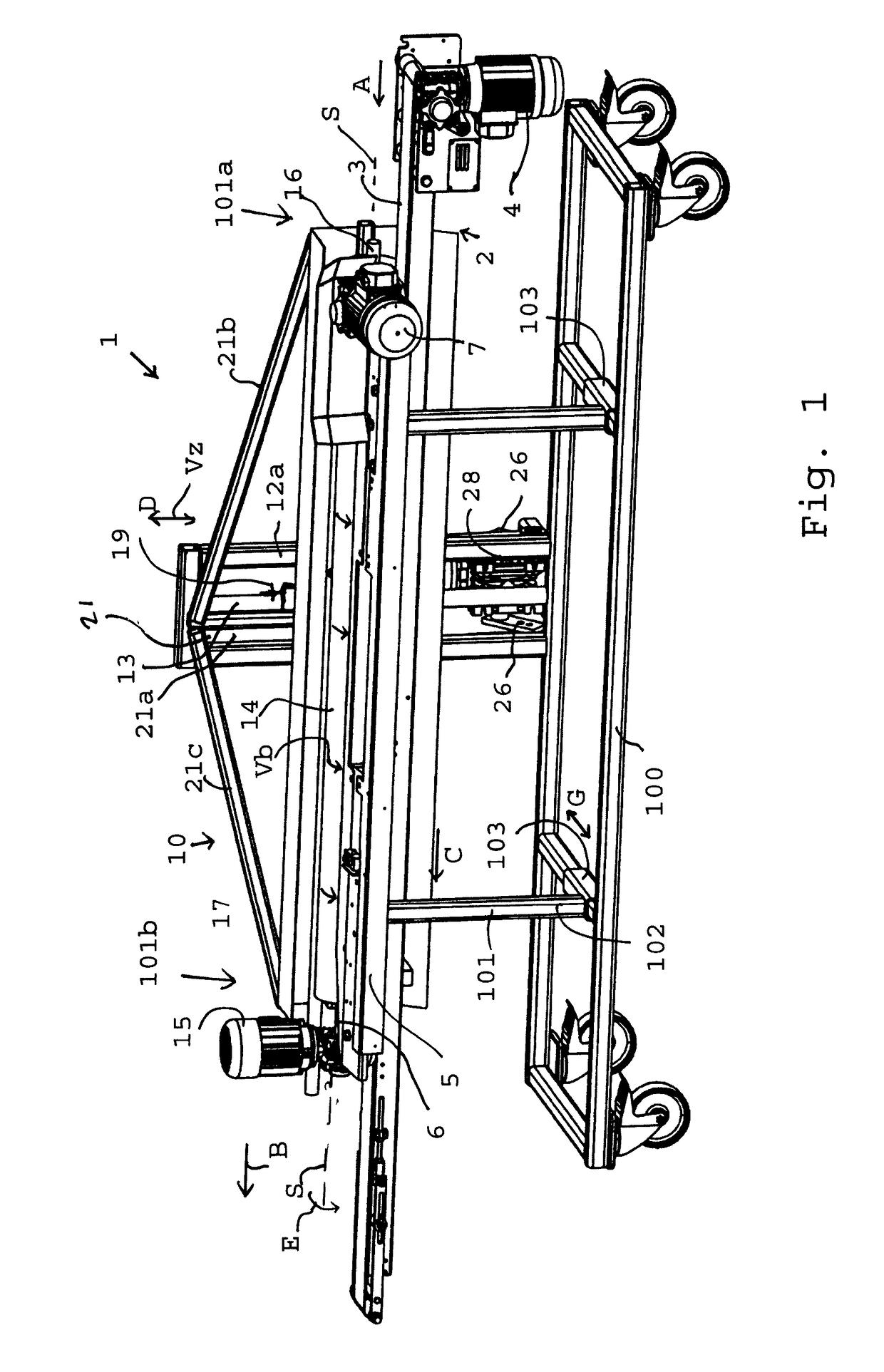
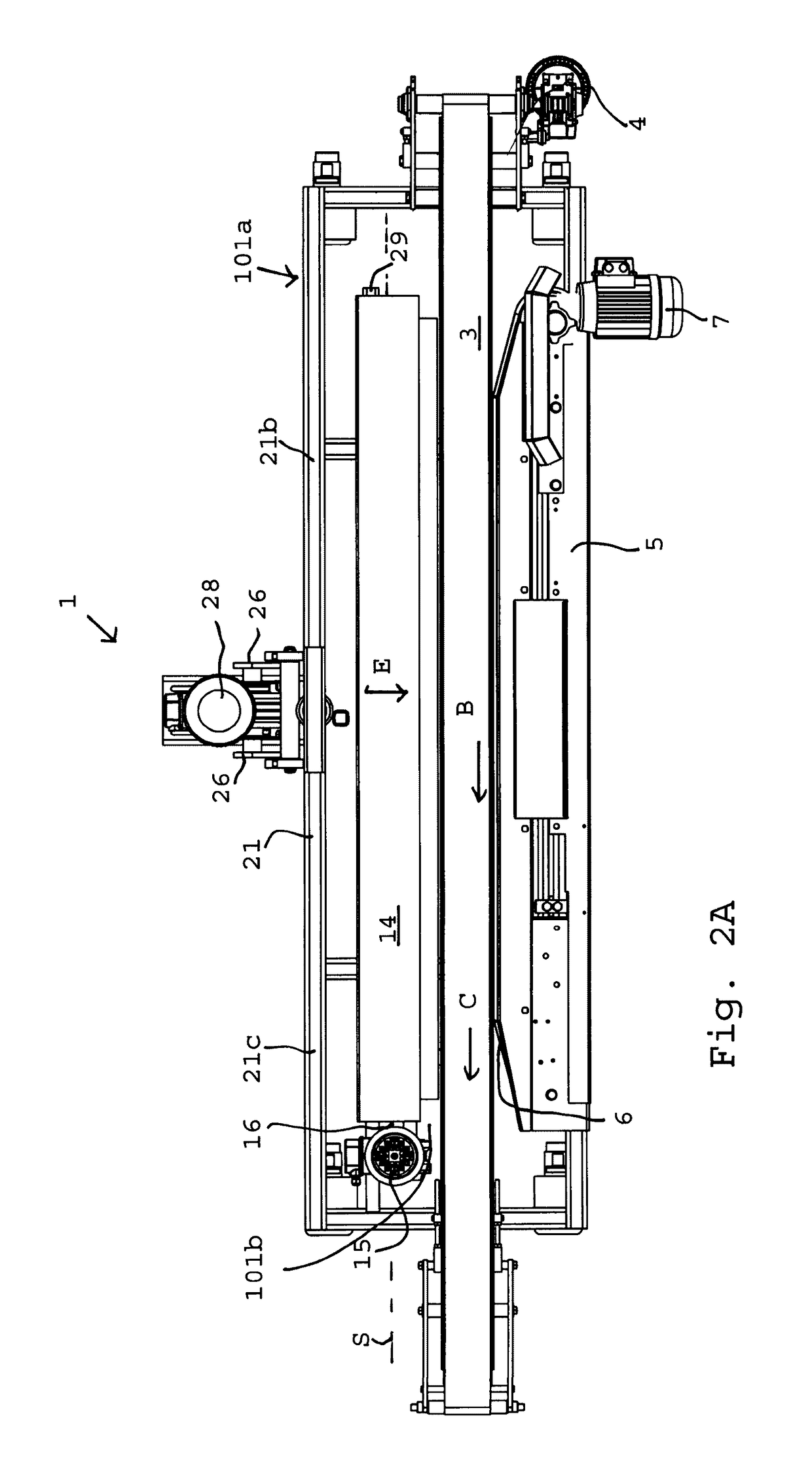
[0041]The device 1 in FIG. 1 comprises a frame 100, to be positioned on a floor, on which frame are supported a belt conveyor 2, a pot rotation device 5 and a brushing device 9.
[0042]The belt conveyor 2 comprises a belt 3 for supporting pots, which belt extends horizontally and forms a pot track between an input end 101a and an output end 101b, and which is driven by an electromotor 4, in the direction B.
[0043]The pot rotation device 5 is positioned adjacent to and diagonally over the belt 3 and comprises a rope belt 6 driven by an electromotor 7 in direction C. The pot rotation device 5 is supported on the frame 100 via columns 101 and tubes 102. The tubes102 can be shifted on transverse tubes 103 of frame 100 and can be secured at the wanted location in order to adjust the horizontal distance of the rope belt 6 to the belt 3, direction G, depending on the pot size. A splashboard 8 screens off the motor 7 from the water and dirt released during the cleaning of pots.
[0044]The brushi...
PUM
 Abstract
- a frame;
- a pot track arranged on the frame, which track extends from an input end to an output end and forms a support surface for the plant pots;
- a movement device for moving the plant pots from the input end to the output end;
- a rotation device for rotating the plant pots about their pot axis;
- a brush for brushing the outer surface of the circumferential wall of the plant pots during the movement;
- a first brush drive for rotating the brush about a lying axis; and
- a second brush drive for moving the rotating brush up and down, while engaging the pot's circumferential wall, between a first position and a second position, wherein the first position is situated at a lower level than the second position.
Description
Claims
Application Information
 - R&D
- Intellectual Property
- Life Sciences
- Materials
- Tech Scout
- Unparalleled Data Quality
- Higher Quality Content
- 60% Fewer Hallucinations
Browse by: Latest US Patents, China's latest patents, Technical Efficacy Thesaurus, Application Domain, Technology Topic, Popular Technical Reports.
© 2025 PatSnap. All rights reserved.Legal|Privacy policy|Modern Slavery Act Transparency Statement|Sitemap|About US| Contact US: help@patsnap.com


