Automatic Floor Cleaning Machine

a floor cleaning machine and automatic technology, applied in the direction of carpet cleaners, instruments, photosensitive materials, etc., can solve the problems of reducing the cleaning effect, increasing the work burden of personnel or the quantity of personnel, and difficult to effectively clean up so as to achieve the effect of cleaning dust particles on the floor reliably

Inactive Publication Date: 2015-01-29
YEJEN APPLIANCES SHENZHEN +1
View PDF3 Cites 15 Cited by
  • Summary
  • Abstract
  • Description
  • Claims
  • Application Information

AI Technical Summary

Benefits of technology

[0006]It is an objective of the present invention to provide an automatic floor cleaning machine for reliably cleaning dust particles on floors. Furthermore, the automatic floor cleaning machine of the present invention can also sweep the dust particles on the floors to kick up the dust particles, and then a vacuum cleaner is used for sucking up the dust particles thoroughly.

Problems solved by technology

However, because manpower has to be allocated, it will increase the work burden of personnel or the quantity of personnel.
1. Corrugations will be formed on the cleaning cloth attached under the top-hat when cleaning is performed. The corrugated cleaning cloth will not be able to lay flatly on the floor surface, and, therefore, the cleaning effect will be reduced.
2. The cleaning cloth sheet can only wipe off the floor during cleaning, and, therefore, dust particles adhered on the floor are difficult to be cleaned up effectively.
3. The cleaning of adjoining surfaces (such as walls or corners) is dependent on the quantity of the cleaning cloth bulges, and therefore the cleaning coverage of the adjoining surfaces is often uneven.

Method used


Image

  • Automatic Floor Cleaning Machine
  • Automatic Floor Cleaning Machine
  • Automatic Floor Cleaning Machine

Examples


first embodiment

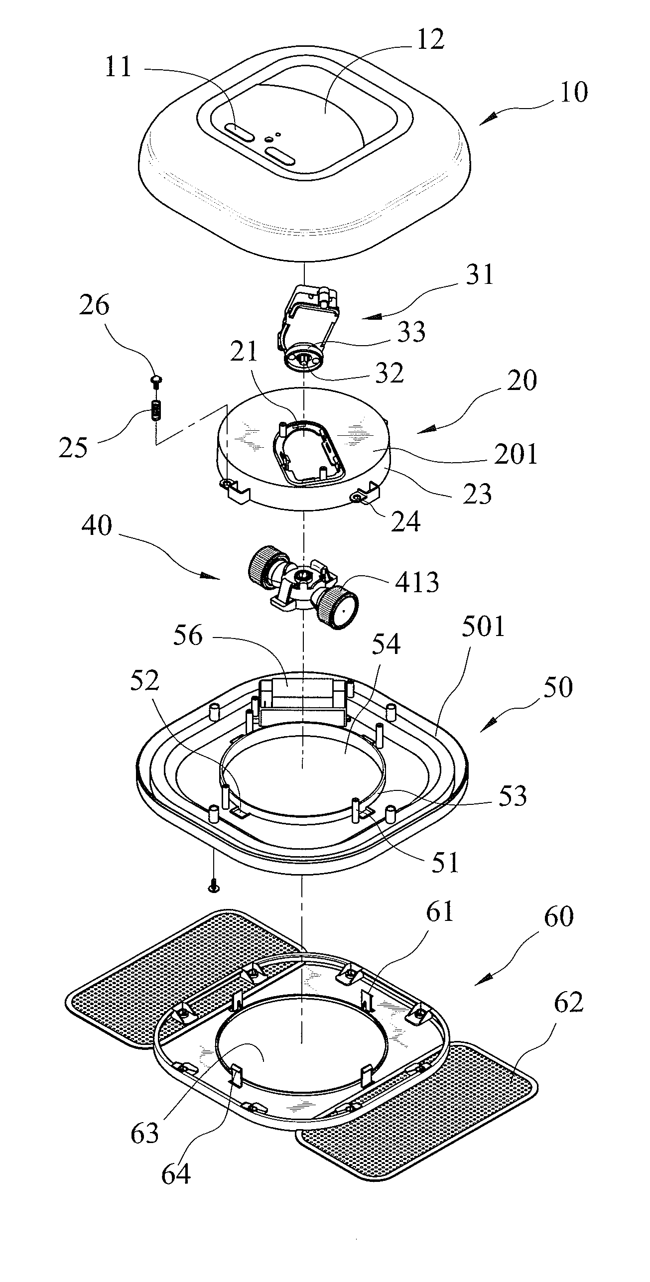
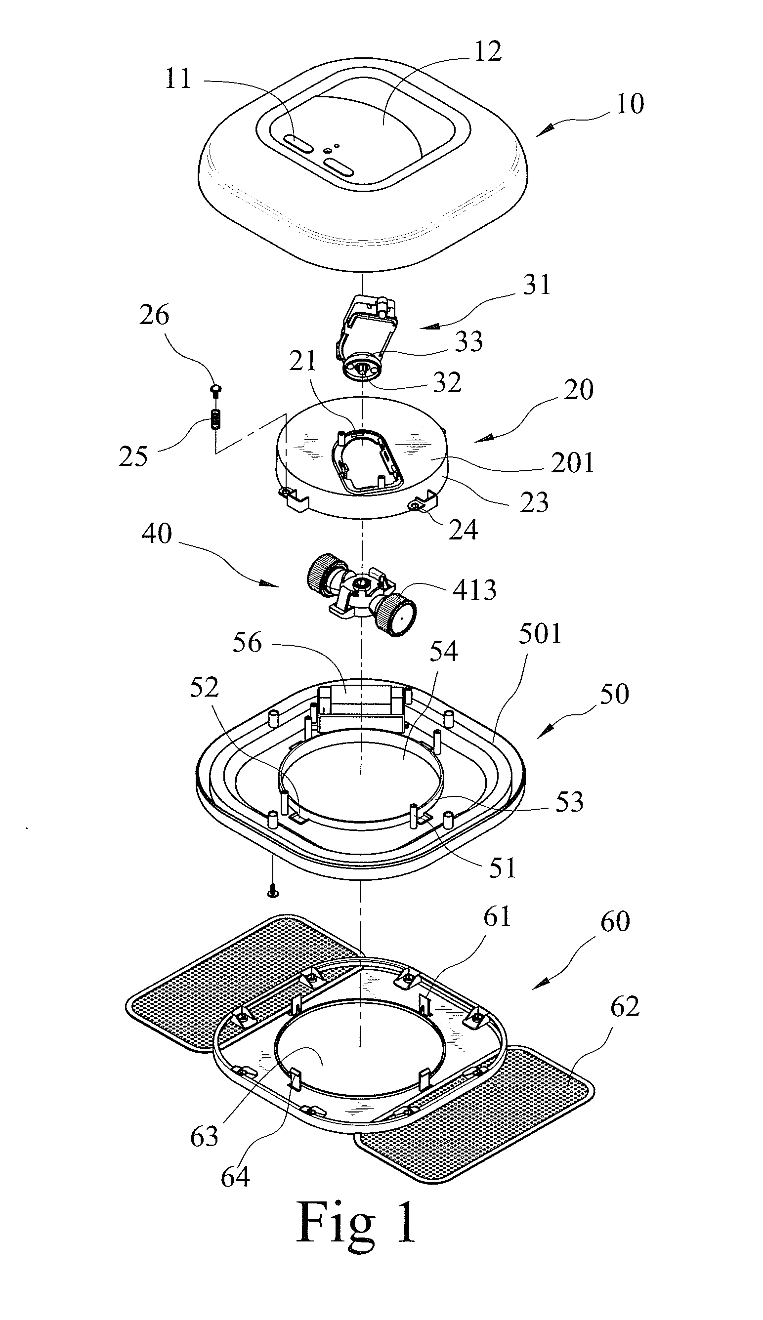
[0025]An automatic floor cleaning machine according to the present invention is shown in FIGS. 1 through 5 of the drawings and includes a base 50, an upper cover 10, a supporting seat 20, a random-turn driving unit 30, and a floor cleaning plate 60. The base 50 includes a disc 501. A circular opening 54 is disposed in a center of the disc 501, and a protruded edge 53 is formed around a circumference of the opening 54. The disc 501 includes a plurality of coupling columns 51 and engaging holes 52 adjacent to coupling columns 51. A power unit 56 is disposed on the disc 501.

[0026]The upper cover 10 is engaged on the base 50, such that an accommodating space (not labeled) is formed between the upper cover 10 and the base 50 for installing the supporting seat 20 and the random-turn driving unit 30. A handle 12 is disposed on a top of the upper cover 10 for convenience of carrying. A switch 11 is also disposed on the top of the upper cover 10 for controlling the startup of the automatic f...

third embodiment

[0033]FIGS. 8 through 12 show an automatic floor cleaning machine according to the present invention. The floor cleaning machine includes a base 50a, an upper cover 10, a supporting seat 20, a random-turn driving unit 30, and two floor cleaning plates 60a. The base 50a includes a disc 501 with a circular opening 54 disposed in a center thereof. A protruded edge 53 is formed around the circumference of the opening 54, and a plurality of indentations 517 is disposed in the protruded edge 53. A plurality of the coupling columns 51 and a power unit 56 are disposed on the disc 501. In this embodiment, a plurality of lugs, each of the lugs with a connecting hole 24, extends outwardly from an outer surface of the circumferential portion 23 of the supporting seat 20. Each coupling column 51 extends through a corresponding connecting hole 24 with the lugs received in the indentations 517 respectively. Then, each coupling column 51 is mounted around by a spring 25 and secured by a screw 26. T...


PUM


Abstract

An automatic floor cleaning machine includes a base, an upper cover covering the base, a supporting seat mounted on the base, a random-turn driving unit installed on the supporting seat, and a floor cleaning plate installed on a bottom of the base. The automatic floor cleaning machine is randomly operated over a floor by the random-turn driving unit. Dedusting papers are disposed on a bottom surface of the floor cleaning plate and protruded from two sides or two corners of the base. The dedusting papers turn to sweep and kick up dust particles on the floor when the automatic floor cleaning machine is operating. Thereby, the effect of thorough cleaning of the floor can be achieved. The automatic floor cleaning machine may further include a vacuum cleaner for further enhancing the cleaning effect.

Description

BACKGROUND OF THE INVENTION[0001]The present invention relates to a floor cleaning equipment and, more particularly, to a floor cleaning machine which can move automatically to clean up dust particles on floors.[0002]Dust particles can often be found on floors in common residential and office buildings. Sweeping by manpower or vacuum cleaner is usually used for cleaning up the dust particles. However, because manpower has to be allocated, it will increase the work burden of personnel or the quantity of personnel. In order to relieve or eliminate the work burden, U.S. Pat. No. 6,938,298 to Turbjorn Aasen discloses a mobile cleaning robot, in which a drive unit is used for random movement, and a Velcro system installed under a top-hat is attached with a cleaning cloth. Thereby, the mobile cleaning robot can be moved on a floor surface for performing random cleaning. Further, the cleaning cloth is soft, so that a small portion of the cleaning cloth bulges because of compression when it...

Claims


Application Information

Patent Timeline
Patent Type & Authority Applications(United States)
IPC IPC(8): A47L11/40
CPCA47L11/4066A47L9/02A47L11/4038A47L11/4069A47L2201/00
Inventor HSU, PEI-CHENG
Owner YEJEN APPLIANCES SHENZHEN
Why Eureka
Try Eureka