Laminated glass

a technology of laminated glass and glass plate, applied in the field of laminated glass, can solve the problems of glass plate breakage and difficulty in visually identifying objects such as landscapes, and achieve the effect of effective surface scratches

Inactive Publication Date: 2017-03-09
ASAHI GLASS CO LTD
View PDF4 Cites 40 Cited by
  • Summary
  • Abstract
  • Description
  • Claims
  • Application Information

AI Technical Summary

Benefits of technology

[0130]In each of Examples and Comparative Examples, grains of sand were pressed and rubbed (about 2,000 iterations) against a glass plate surface by a force of about 10 N. Thereafter, the effectiveness against scratches on the surface was eva

Problems solved by technology

In other words, immediately after formation of flaws having a depth of DOL or greater, cracks rapidly grow to everywhere throughout the in-plane of the glass plate because of high CT, thereby causing breakage of the glass plate.

Method used


Image

  • Laminated glass
  • Laminated glass
  • Laminated glass

Examples


first embodiment

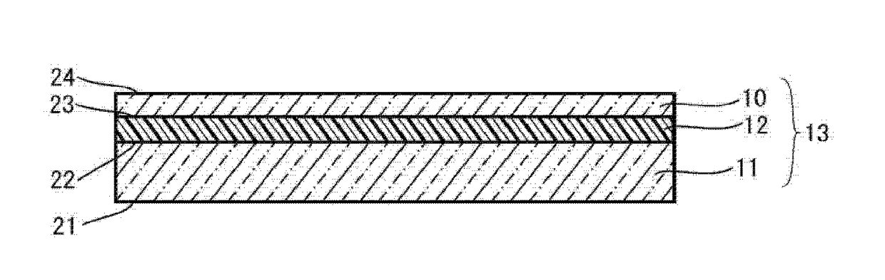
[0021]FIG. 1 is a cross-sectional view showing schematically the structure of a laminated glass 13 according to an embodiment of the present invention. As shown in FIG. 1, the laminated glass 13 according to an embodiment of the present invention is structured to include a first glass plate 11, a second glass plate 10 and an intermediate layer 12 provided between the first glass plate 11 and the second glass plate 10.

[0022]The first glass plate 11 has a first face 21 and a second face 22 opposing the first face 21. And the second glass plate 10 has a third face 23 and a fourth face 24 opposing the third face 23. The intermediate layer 12 is provided between the second face 22 of the first glass plate 11 and the third face 23 of the second glass plate 10, and bonds both the glass plates. In other words, the second face 22 and the third face 23 are bonding faces, and the first face 21 and the fourth face 25 are exposed faces.

[0023]Incidentally, in this embodiment, the first face 21 is...

examples

[0121]The present invention is described in detail below by reference to Examples, but the present invention should not be construed as being limited to these Examples.

(1) Production of Second Glass Plate

[0122]Glass produced by a float process for use in chemical strengthening was cut and divided, and then ground with a #1000 grindstone into glass plates having thicknesses shown in Table 1. Thereafter, the glass plates were subjected to ion exchange treatment by using potassium nitrate under the conditions set forth in Table 1, and then physical properties of the thus obtained chemically-strengthened glass plates were evaluated. As to the glass compositions, those within the range of (i) and (ii) among the compositions exemplified hereinbefore were used.

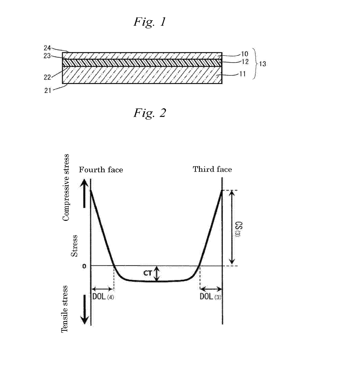
[0123]The surface compressive stress (CS) and the depth of compressive stress (DOL) were measured with a glass surface stress meter (FSM-6000LE, manufactured by ORIHARA INDUSTRIAL CO., LTD.). Additionally, the tensile stress (CT) was...


PUM

PropertyMeasurementUnit
Thicknessaaaaaaaaaa
Thicknessaaaaaaaaaa
Thicknessaaaaaaaaaa

Abstract

The present invention relates to a laminated glass including a first glass plate, a second glass plate and an intermediate layer provided between the first glass plate and the second glass plate, in which the first glass plate has a first face and a second face opposing the first face, the second glass plate has a third face and a fourth face opposing the third face, the intermediate layer is provided between the second face and the third face, the second glass plate is a chemically-strengthened glass, and in the second glass plate, when a compressive stress on the third face is denoted as CS(3), a tensile stress generated in an interior of the second glass plate is denoted as CT, a thickness of the second glass plate is denoted as t, a depth of the compressive stress on a side of the third face is denoted as DOL(3) and a depth of a compressive stress on a side of the fourth face is denoted as DOL(4), CS(3)/[CT2×{t−(DOL(3)+DOL(4))}] is greater than 1.1 MPa−1×mm−1.

Description

FIELD OF THE INVENTION[0001]The present invention relates to a laminated glass.BACKGROUND OF THE INVENTION[0002]Laminated glass has been widely used for windowpanes and as glazing in application to transportation vehicles such as automobiles, transit rail cars and airplanes, and in application to architectural structures. The glazing is a transparent or translucent member of a wall or other structures. One and / or two glass plates used for a laminated glass are often strengthened by air cooling for a purpose of enhancing mechanical strength such as scratch resistance, thereby forming surface compressive stress. In transportation uses in particular, recent years have seen weight-reduction requirements for laminated glass currently in use from the viewpoint of enhancing fuel efficiency and traveling stability.[0003]In general, forming laminated glass through the use of a thin glass plate might be conducive to achieving light weight, but there arises a problem that, when a thin glass pl...

Claims


Application Information

Patent Timeline
IPC IPC(8): B32B17/06
CPCB32B2605/00B32B17/06C03C27/10B32B17/10036B32B17/10137B32B17/10761B32B17/10788
Inventor NOTSU, KEIJINISHIHAMA, JIROSADAKANE, SHUNSUKENARITA, MAKOTONAKAGAWA, KOJISAKAI, YUSUKEHATANO, MAYA
Owner ASAHI GLASS CO LTD
Why Eureka
Try Eureka