Measuring device, biological testing device, flow velocity measuring method, and pressure measuring method

Inactive Publication Date: 2011-12-29
SEIKO EPSON CORP
View PDF7 Cites 19 Cited by
  • Summary
  • Abstract
  • Description
  • Claims
  • Application Information

AI Technical Summary

Benefits of technology

[0050]According to the aspect described above, as with the aspects described in the foregoing, it is possible to readily obtain the maximum frequency shift amount corresponding to an optimum ultrasound incidence

Problems solved by technology

Also, the error is known to decrease as γ decreases.
Therefore, according to those publications, a problem is presented in that a user with no professional knowledge will be unable to readily set the ultrasound incidence angle γ to an optimum level, and will be unable to obtain an optimum frequency shift amount to measure the blood flow to a high degree of accuracy.
However, a complex configuration becomes necessary to perform image processing.
A problem is also presented in that an au

Method used


Image

  • Measuring device, biological testing device, flow velocity measuring method, and pressure measuring method
  • Measuring device, biological testing device, flow velocity measuring method, and pressure measuring method
  • Measuring device, biological testing device, flow velocity measuring method, and pressure measuring method

Examples


first embodiment

[0078]A biological testing device comprising a measuring device having an ultrasonic sensor according to the first embodiment of the present invention will now be described with reference to the accompanying drawings.

1. Overall Configuration of Biological Testing Device

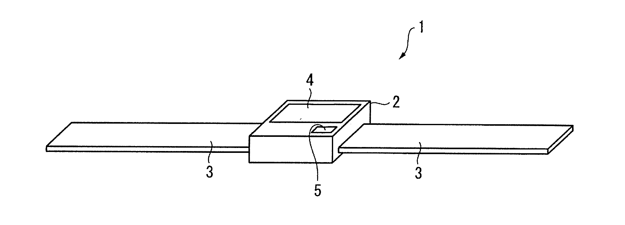
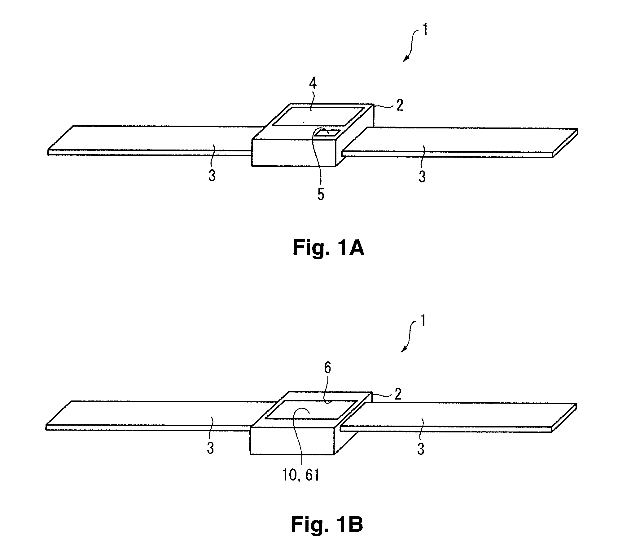
[0079]FIGS. 1A and 1B are perspective views showing an overview of a biological testing device according to a first embodiment, where FIGS. 1A and 1B are views showing a front surface side and a back surface side of the biological testing device, respectively.

[0080]In FIGS. 1A and 1B, a biological testing device 1 is a device for using ultrasound to measure the state of a blood vessel, and specifically, a device for measuring the flow velocity of blood flowing in the blood vessel (i.e., blood flow velocity), the blood being a fluid to be measured. As shown in FIGS. 1A and 1B, the biological testing device 1 comprises a main device body 2, and a band 3 connected to the main device body 2. The biological testing device ...

second embodiment

[0205]Next, the biological testing device according to the second embodiment of the present invention will be described with reference to the accompanying drawings. In the biological testing device 1 according to the first embodiment described above, the blood flow velocity was measured as the state of the blood vessel. However, in the biological testing device 1 according to the second embodiment, blood pressure, in addition to the blood flow velocity described above, is measured as a state of the blood vessel. In the description for the second embodiment and subsequent embodiments, configurations that are the same as those in the first embodiment are labeled with the same numerals, and corresponding descriptions are omitted or simplified.

1. Configuration of Biological Testing Device

[0206]The biological testing device 1 according to the second embodiment has substantially the same configuration as the first embodiment, and comprises the main device body 2 and the band 3 connected t...

third embodiment

[0245]Next, a biological testing device that is a measuring device according to the third embodiment of the present invention will now be described with reference to the accompanying drawings.

[0246]FIG. 18 is a top view showing the plane of the substrate of an ultrasonic sensor 10A of the biological testing device according to the third embodiment of the present invention.

[0247]In the biological testing device 1 according to the first embodiment and the second embodiment described above, reception data based on the reception signal inputted from the ultrasonic sensor 10 is used to obtain the vector V1V2, perform measurement of the position of the blood vessel, and computationally obtain the vascular diameter D. In contrast, in the biological testing device 1 according to the third embodiment, the ultrasonic sensor 10A has position-measuring ultrasonic arrays 17 for measuring the position of the blood vessel and the vascular diameter, arranged on outer peripheral sides of the ultraso...


PUM


Abstract

A measuring device includes an ultrasonic sensor with ultrasonic arrays each having a linear array structure in which ultrasonic elements are arranged along a linear scanning direction with the linear scanning directions of at least two of the ultrasonic arrays being different from each other, a transmission/reception control unit that controls transmission/reception of ultrasonic waves by the ultrasonic arrays, and a computation part that measures a frequency shift amount based on a reception signal from the ultrasonic arrays. The transmission/reception control unit includes a signal delay circuit that controls a transmission angle of ultrasonic waves. The computation part includes a frequency shift amount calculating part that calculates, for each of the ultrasonic arrays, a frequency shift amount based on a reception signal from each of the ultrasonic arrays, and a maximum shift amount obtaining part that obtains a maximum frequency shift amount from the calculated frequency shift amounts.

Description

CROSS-REFERENCE TO RELATED APPLICATIONS[0001]This application claims priority to Japanese Patent Application No. 2010-145107 filed on Jun. 25, 2010. The entire disclosure of Japanese Patent Application No. 2010-145107 is hereby incorporated herein by reference.BACKGROUND[0002]1. Technical Field[0003]The present invention relates to a measuring device, a biological testing device, a flow velocity measuring method, and a pressure measuring method for using ultrasound to measure the state of an object to be measured.[0004]2. Related Art[0005]The ultrasound Doppler method is conventionally known as a method for measuring the velocity of movement of a fluid using ultrasound. This ultrasound Doppler method is a method in which ultrasound having a predetermined frequency is directed on a fluid, and the flow velocity is obtained from the amount by which the frequency of the resulting reflected wave shifts. The flow velocity can be obtained using a relationship shown in the following Equatio...

Claims


Application Information

Patent Timeline
IPC IPC(8): A61B8/06
CPCA61B8/04A61B8/06A61B8/4483A61B8/4461A61B8/4472A61B8/4227
Inventor TSURUNO, JIRO
Owner SEIKO EPSON CORP
Why Eureka
Try Eureka