Firearm suppressor

a suppressor and firearm technology, applied in the field of suppressors, can solve the problems of not always being as effective as desired, and the configuration of firing produces a tremendous amount of expanding gas and subsequent hea

Active Publication Date: 2017-03-09
STEALTH PROJECT LLC
View PDF3 Cites 33 Cited by
  • Summary
  • Abstract
  • Description
  • Claims
  • Application Information

AI Technical Summary

Benefits of technology

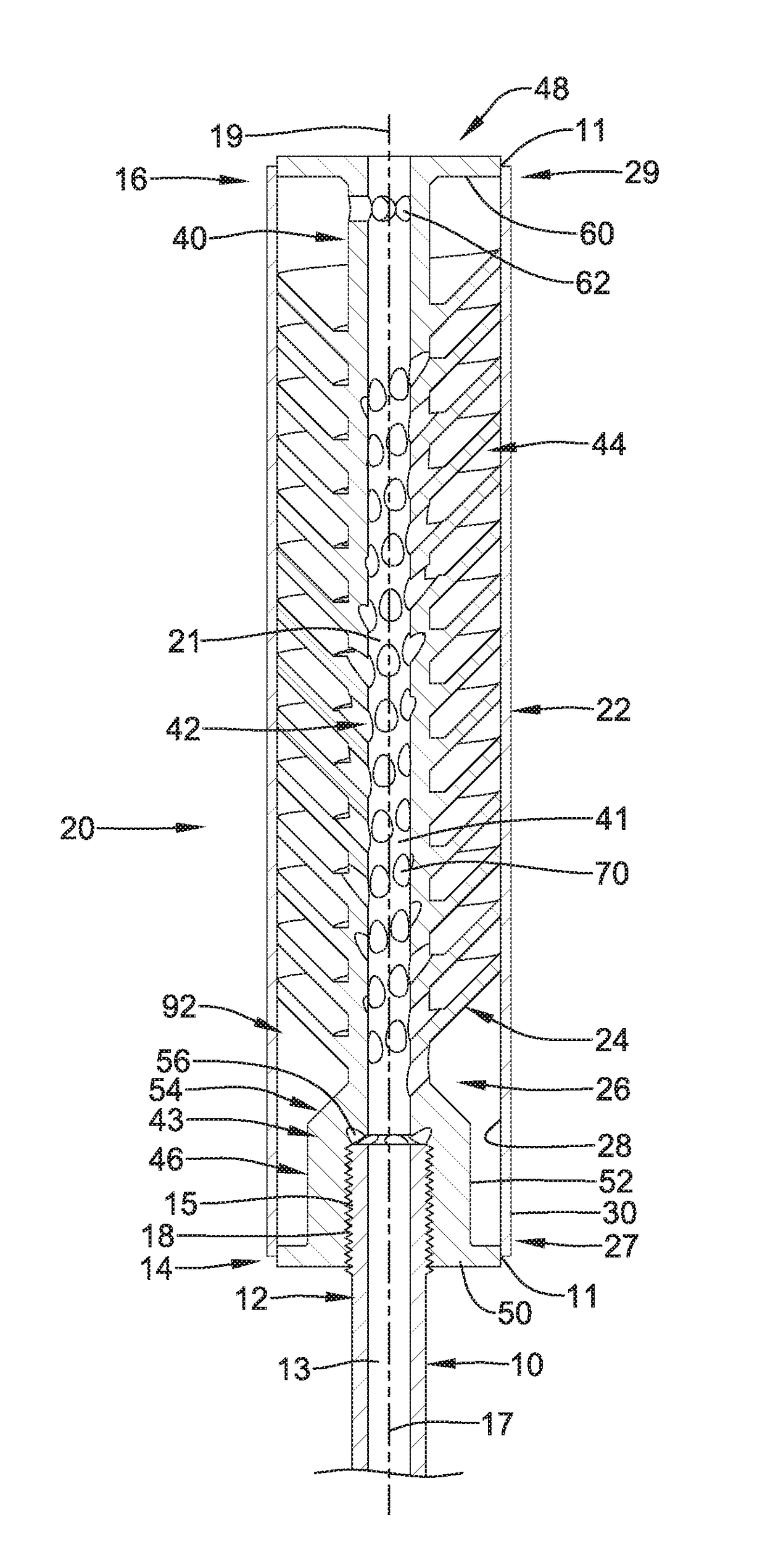
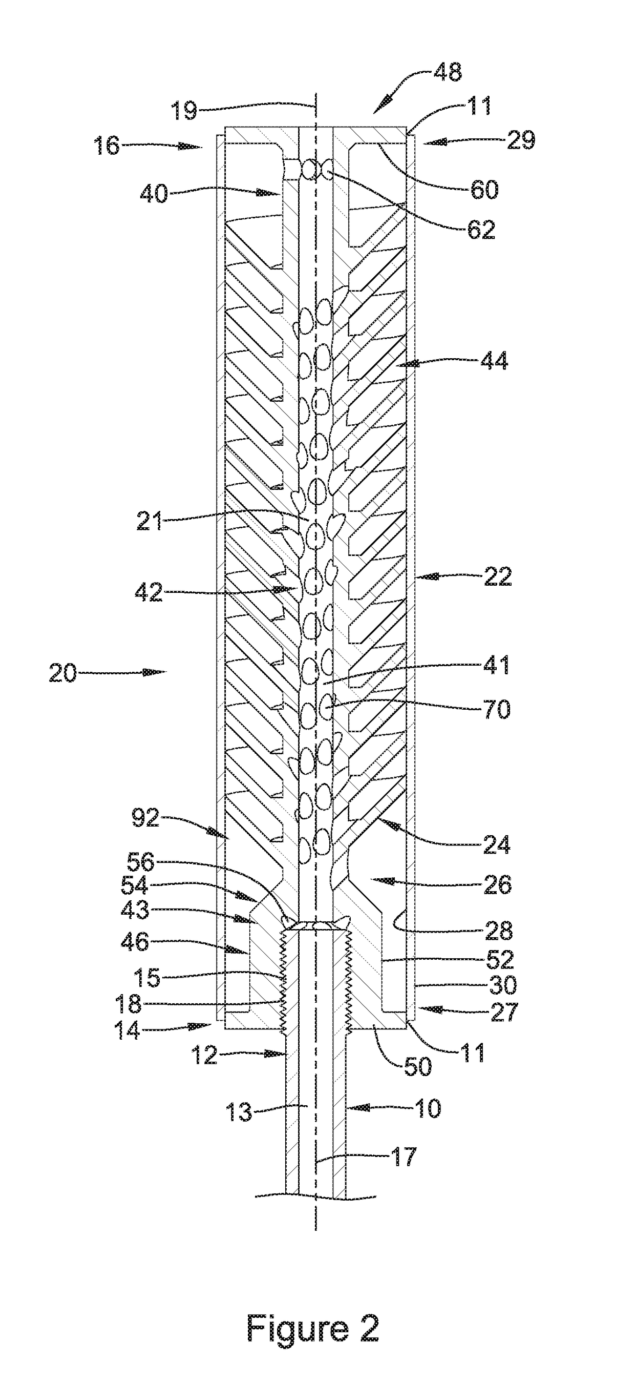
[0017]Yet additional other embodiments relate to a firearm suppressor including a cylindrical body portion including a cylindrical wall having a proximal end designed to be coupled to a firearm and a distal end. The cylindrical wall extending along a central longitudinal axis from the proximal end to the distal end, the cylindrical wall defining a central bore extending from the proximal end to the distal end about the longitudinal axis. The proximal end of the cylindrical wall defines one or more cooling bores spaced from the central bore, the cooling bores extending into the annular wall offset from the central longitudinal axis.
[0018]The above summary of some embodiments is not intended to describe each disclosed embodiment or every implementation of the present disclosure. The Figures, and Detailed Description, which follow, more particularly exemplify some of these embodiments.

Problems solved by technology

This “firing” produces a tremendous amount of expanding gases and subsequent heat, caused from the combustion of the propellant used in the firearm to accelerate a projectile.
However, such configurations are not always as effective as desired.

Method used


Image

  • Firearm suppressor
  • Firearm suppressor
  • Firearm suppressor

Examples


Embodiment Construction

[0036]For the following defined terms, these definitions shall be applied, unless a different definition is given in the claims or elsewhere in this specification.

[0037]All numeric values are herein assumed to be modified by the term “about,” whether or not explicitly indicated. The term “about” generally refers to a range of numbers that one of skill in the art would consider equivalent to the recited value (e.g., having the same function or result). In many instances, the terms “about” may include numbers that are rounded to the nearest significant figure.

[0038]The recitation of numerical ranges by endpoints includes all numbers within that range (e.g. 1 to 5 includes 1, 1.5, 2, 2.75, 3, 3.80, 4, and 5).

[0039]As used in this specification and the appended claims, the singular forms “a”, “an”, and “the” include plural referents unless the content clearly dictates otherwise. As used in this specification and the appended claims, the term “or” is generally employed in its sense inclu...


PUM


Abstract

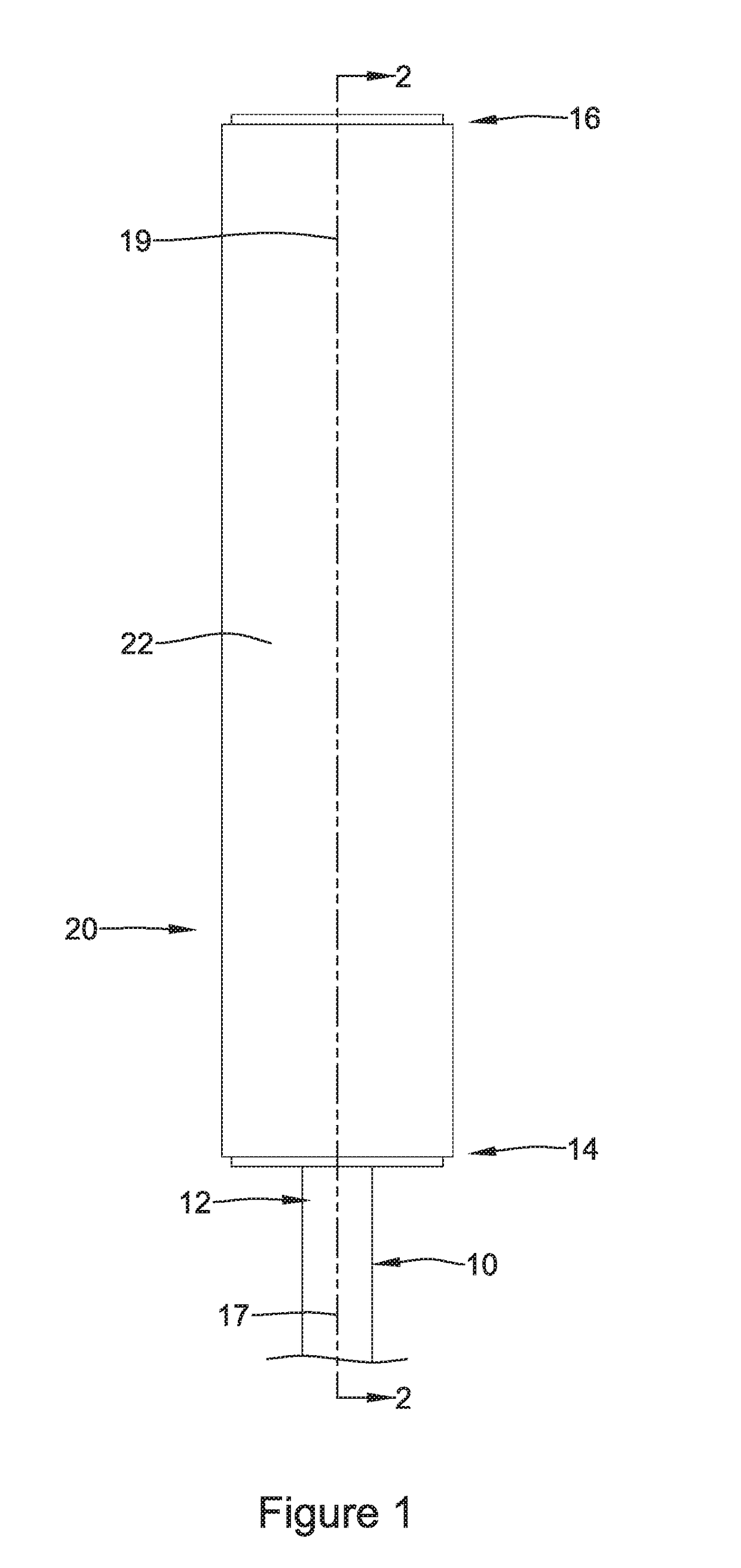
Disclosed herein are suppressors for use with firearms or the like, and methods of making and using such firearm suppressors. Some aspects relate to a firearm suppressor including a helical portion extending helically around a cylindrical body portion, at least a section of the helical portion being canted such that it extends radially outward from the cylindrical body portion at an oblique angle relative to a plane normal to the central longitudinal axis. In some cases, the helical portion is canted distally.
In another respect, a firearm suppressor including a helical portion extending radially outward from and helically around a cylindrical body portion having a bore to define a crest and a root, and at least one channel extends from an inner opening along the bore to an outer opening along the root of the helical portion.
In yet another respect, a firearm suppressor including a cylindrical wall defining a central bore extending about a longitudinal axis, and one or more cooling bores spaced from the central bore, the cooling bores extending into the wall offset from the central longitudinal axis.

Description

CROSS-REFERENCE TO RELATED APPLICATIONS[0001]This application claims priority under 35 U.S.C. §119 to U.S. Provisional Application Ser. No. 62 / 283,539 filed Sep. 4, 2015, the entire disclosure of which is incorporated herein by reference.TECHNICAL FIELD[0002]The present disclosure pertains to suppressors, and methods for using and manufacturing the same. More particularly, the present disclosure pertains to a suppressor for attachment to a weapon, such as a firearm or the like, and methods for manufacturing and using such devices.BACKGROUND[0003]Firearms produce a loud concussive sound and bright flash when a projectile leaves the distal end or muzzle of a firearm barrel when fired. This “firing” produces a tremendous amount of expanding gases and subsequent heat, caused from the combustion of the propellant used in the firearm to accelerate a projectile.[0004]Suppressors, for use with various firearms, are generally known. Suppressors may absorb, dissipate and / or reduce the audible...

Claims


Application Information

Patent Timeline
Patent Type & Authority Applications(United States)
IPC IPC(8): F41A21/30F41A21/34F41A21/24
CPCF41A21/30F41A21/34F41A21/24
Inventor SLACK, MICHAEL B.
Owner STEALTH PROJECT LLC
Why Eureka
Try Eureka