Door latch assembly

Inactive Publication Date: 2017-03-23
THASE ENTERPRISE CO LTD
View PDF4 Cites 3 Cited by
  • Summary
  • Abstract
  • Description
  • Claims
  • Application Information

AI Technical Summary

Benefits of technology

The present invention provides a door latch assembly with a simplified structure that allows the user to operate it with less force. It can be easily assembled by workers. The assembly includes a push bar mechanism, a latch mechanism, and a linking device that helps move the push bar away from the bracket and casing when released. The sliding member can be moved or actuated by the actuating element when it is rotated. These technical effects make the door latch assembly more user-friendly and easy to assemble, resulting in improved efficiency and user experience.

Problems solved by technology

However, normally, it takes a great force for forcing or moving the latch tongue or latch bolt of the door latch assembly from the door frame such that the latch tongue or latch bolt of the door latch assembly may not be easily actuated or operated by the user with a decreased force.

Method used


Image

  • Door latch assembly
  • Door latch assembly
  • Door latch assembly

Examples


Embodiment Construction

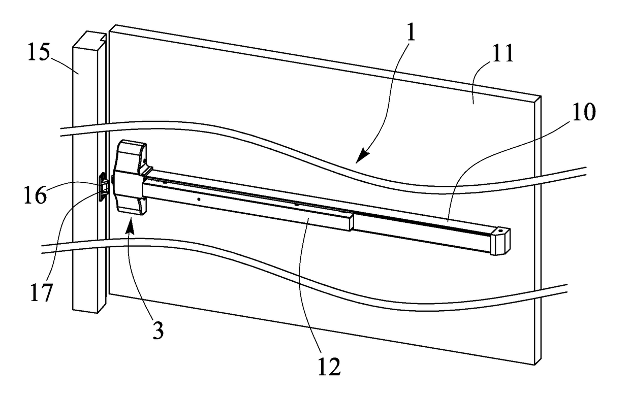
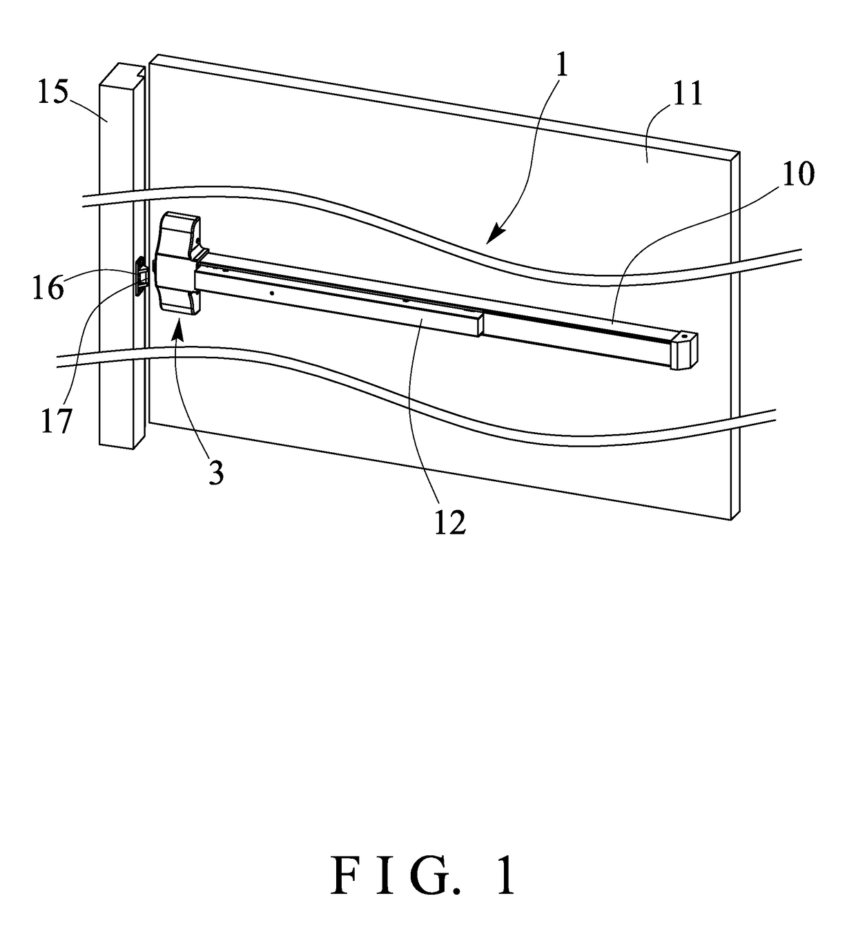
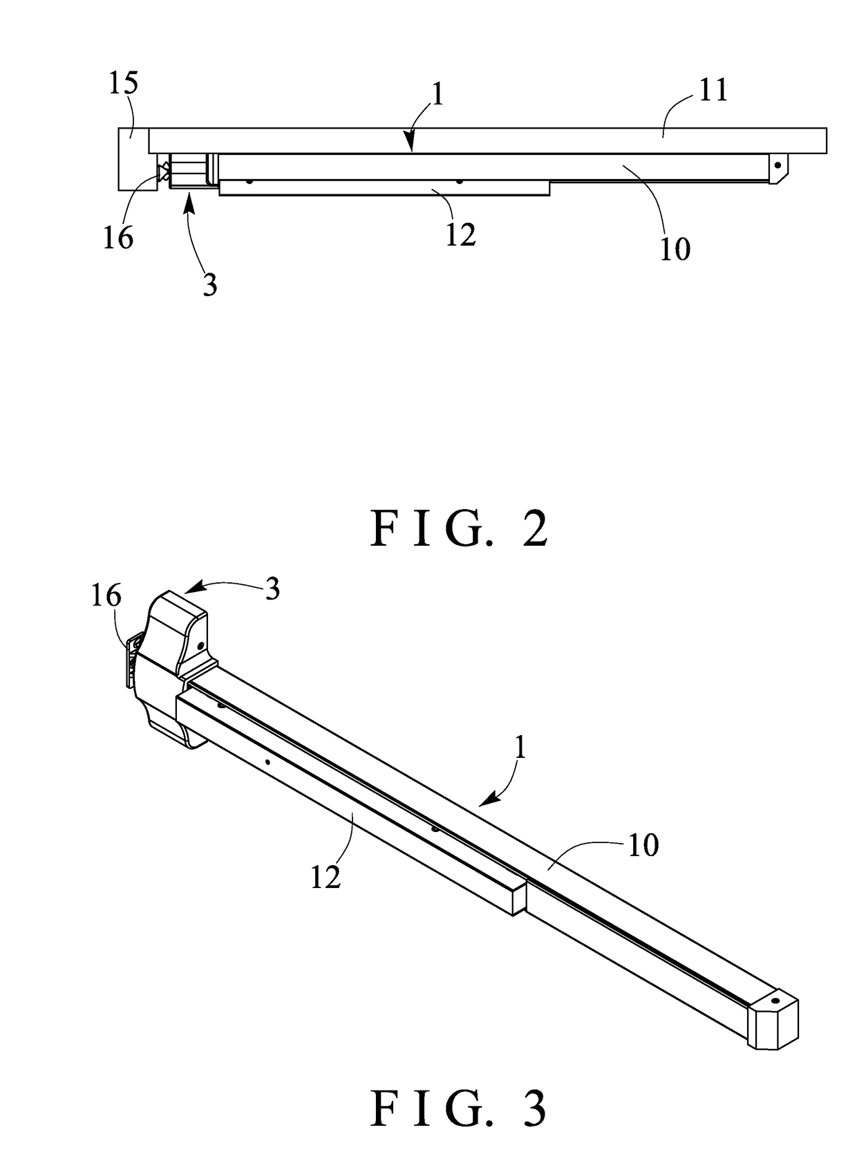
[0032]Referring to the drawings, and initially to FIGS. 1-6, a door latch assembly in accordance with the present invention comprises a push bar mechanism 1 including a box or casing 10 attached or mounted to the middle or intermediate portion at an inner or indoor portion of a door panel 11 (FIGS. 1, 2), such as an exit door panel 11, a push bar 12 slidably attached or mounted to the casing 10, and a base plate 13 (FIGS. 6, 16-17) is disposed or engaged into an inner chamber 14 of the casing 10 and mounted or secured to the casing 10 with screws or catches or fasteners (not illustrated) or the like, or formed integral with the casing 10, one or more (such as two) linking devices 20 are connected or coupled between the push bar 12 and the base plate 13 and / or the casing 10.

[0033]For example, as shown in FIGS. 4-8 and 11-12, the linking devices 20 each include a bracket 21 disposed or engaged into the chamber 14 of the casing 10 and mounted or secured to the casing 10 with catches or...


PUM


Abstract

A door latch assembly includes a push bar attached to a door panel and connected to an actuating lever, a latch mechanism is attached to the door panel and includes an actuating element, a housing is attached to the seat panel, a rotary latch member is rotatably attached to the housing for engaging with a keeper member, a sliding member is slidably connected to the actuating lever for selectively locking the rotary latch member to the keeper member and for selectively latching the door panel to the door frame, and for allowing the sliding member to be moved away from the rotary latch member with the actuating lever when the push bar is moved toward the casing.

Description

BACKGROUND OF THE INVENTION[0001]1. Field of the Invention[0002]The present invention relates to a door latch assembly for a panic exit door, and more particularly to a door latch assembly for a panic exit door including an improved and simplified structure or configuration for allowing the door latch assembly to be easily actuated or operated by the user.[0003]2. Description of the Prior Art[0004]Various kinds of typical door latch assemblies for panic exit doors have been developed and provided for latching or locking the exit doors and comprise a push bar connected or coupled to a door latch assembly for actuating or operating the door latch assembly to lock and release the exit doors.[0005]For example, U.S. Pat. No. 3,614,145 to Zawadzki, U.S. Pat. No. 3,877,262 to Williams, U.S. Pat. No. 4,709,950 to Zortman, U.S. Pat. No. 4,796,931 to Heid, U.S. Pat. No. 5,219,385 to Yeh, U.S. Pat. No. 5,605,362 to Surko, Jr., U.S. Pat. No. 6,009,732 to Haeck et al., and U.S. Pat. No. 6,032,98...

Claims


Application Information

Patent Timeline
IPC IPC(8): E05B65/10
CPCE05B65/1093E05B65/1073E05B65/1046
Inventor LIN, CHING TIEN
Owner THASE ENTERPRISE CO LTD
Why Eureka
Try Eureka