Image forming apparatus
a technology of image forming and forming apparatus, which is applied in the direction of electrographic process apparatus, instruments, optics, etc., can solve the problems of lead edge timing shift, double height, skew or offset shift of paper,
- Summary
- Abstract
- Description
- Claims
- Application Information
AI Technical Summary
Benefits of technology
Problems solved by technology
Method used
Image
Examples
first embodiment
Example of Configuration of Image Forming Apparatus 100
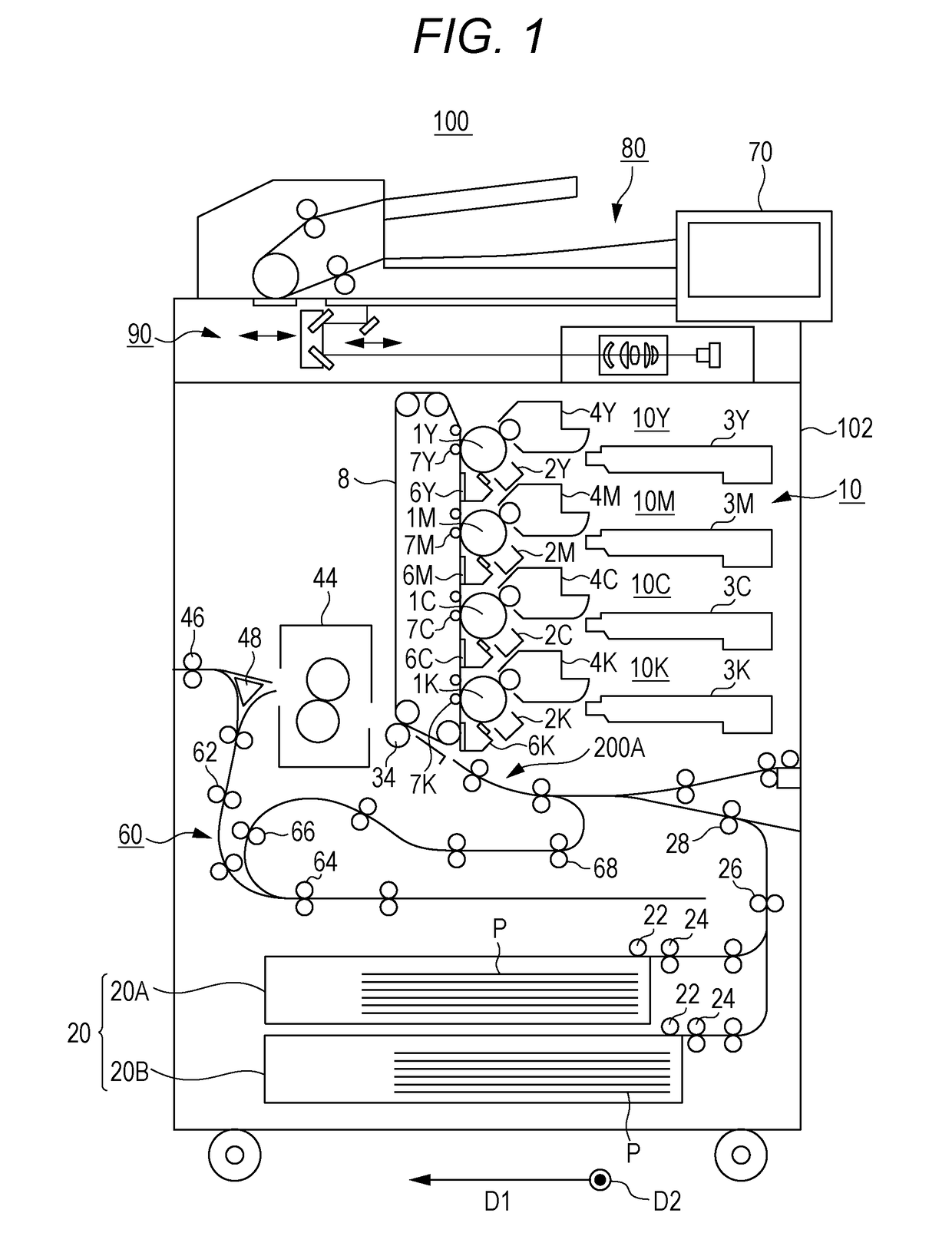
[0038]FIG. 1 illustrates an example of the configuration of an image forming apparatus 100 according to the present invention. As illustrated in FIG. 1, the image forming apparatus 100 is what is called a tandem image forming apparatus and includes an automatic document feeder 80 and an apparatus body 102. The automatic document feeder 80 is mounted on top of the apparatus body 102 and uses a conveyance roller or the like to feed paper set on a conveyance stage to an image reading unit 90 of the apparatus body 102.
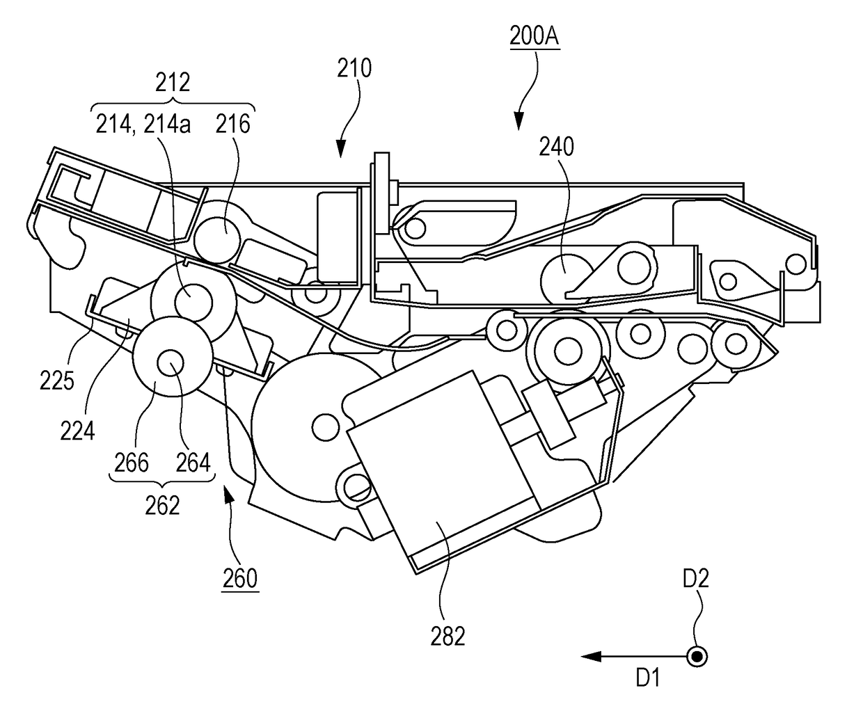
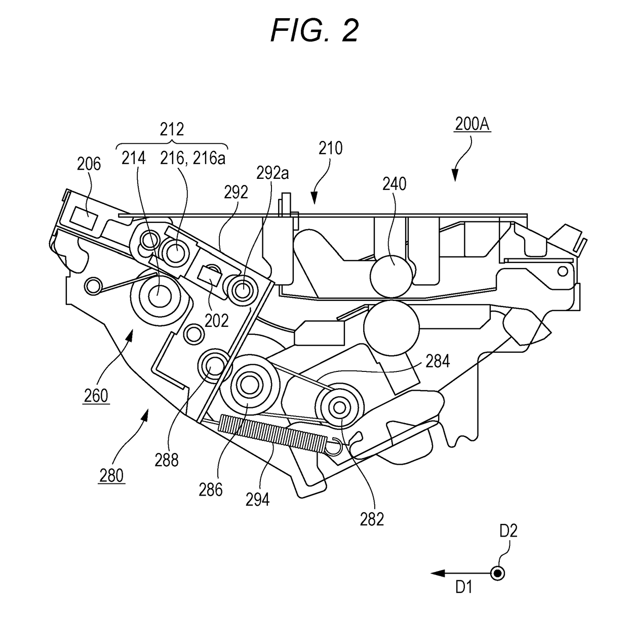
[0039]The apparatus body 102 includes an operation display unit 70, the image reading unit 90, an image forming unit 10, an intermediate transfer belt 8, a paper feeding unit 20, a registration unit 200A, a fixing unit 44, and an auto duplex unit (hereinafter referred to as an ADU) 60.
[0040]The operation display unit 70 includes a touch panel formed of a combination of a display unit and an input unit and a plurality o...
second embodiment
[0131]In a second embodiment, a nip load of a registration roller pair 212 is adjusted by using a pressing / separation mechanism 380 instead of using a backup member 262 and the like as described in the first embodiment. Note that the other configuration and operation of an image forming apparatus 100 including a registration unit 200B are similar to those of the first embodiment, whereby a detailed description of a common component will be omitted.
[0132][Example of Configuration of Pressing / Separation Mechanism 380]
[0133]FIG. 14 illustrates an example of the configuration of the registration unit 200B according to the second embodiment. Each of FIGS. 15A and 15B illustrates an example of the configuration of the pressing / separation mechanism 380.
[0134]In the second embodiment, a nip load adjustment mechanism 260 adjusting the nip load of the registration roller pair 212 is formed of the pressing / separation mechanism 380. The pressing / separation mechanism 380 is obtained by partially...
third embodiment
[0187]In a third embodiment, a nip load of a registration roller pair 212 is adjusted by a configuration different from that of the pressing / separation mechanism 380 of the second embodiment. Note that the other configuration and operation of an image forming apparatus 100 including a registration unit 200C are similar to those of the first and second embodiments, whereby a detailed description of a common component will be omitted.
[0188][Example of Configuration of Pressing / Separation Mechanism 480]
[0189]FIG. 21 illustrates an example of the configuration of the registration unit 200C according to the third embodiment. FIG. 21 illustrates a state of a pressing / separation mechanism 480 when releasing the nip of the registration roller pair 212. FIG. 22 illustrates an example of the configuration of the pressing / separation mechanism 480.
[0190]In the third embodiment, a nip load adjustment mechanism 260 adjusting the nip load of the registration roller pair 212 is formed of the pressi...
PUM
 Abstract
Description
Claims
Application Information
 - R&D
- Intellectual Property
- Life Sciences
- Materials
- Tech Scout
- Unparalleled Data Quality
- Higher Quality Content
- 60% Fewer Hallucinations
Browse by: Latest US Patents, China's latest patents, Technical Efficacy Thesaurus, Application Domain, Technology Topic, Popular Technical Reports.
© 2025 PatSnap. All rights reserved.Legal|Privacy policy|Modern Slavery Act Transparency Statement|Sitemap|About US| Contact US: help@patsnap.com


