
Rotable and pivotable medical instrument

a medical instrument and pivoting technology, applied in the field of medical instruments, can solve the problem of extreme slender shaft design

Active Publication Date: 2019-07-23
KARL STORZ GMBH & CO KG
View PDF48 Cites 0 Cited by
  • Summary
  • Abstract
  • Description
  • Claims
  • Application Information

AI Technical Summary

Benefits of technology

[0013]The coaxial design allows the two actuation elements to be arranged within a very narrow space in the shaft, such that extremely slender shafts are possible. The coaxial design opens up the possibility of providing an inner central actuation element which consists of a compact rod-shaped body with tensile and compressive strength, for example in the form of a wire or a rod. Through this compact body it is possible to transmit relatively high compressive and tensile forces, which are needed to close the movable jaw part with the necessary force such that the tissue held in between, for example cartilage, can be severed. The further actuation element, which coaxially surrounds the central actuation element, can be designed for example as a tubular body which, by virtue of its geometry, can exert relatively high tensile and compressive forces. This outer actuation element can be used to pivot the jaw head. The forces needed for this are substantially less than the forces for closing a jaw part. However, the pivotable jaw part can be opposed by the corresponding abutment against which the closing movable jaw part strikes. The outer element can, however, be made with a relatively thin wall. This results overall in an extremely slender design of the shaft. In addition, it is possible for the jaw head area to be made relatively short.
[0056]This measure has the advantage of offering yet another degree of freedom, namely rotatability between shaft and handle. The handle, especially if designed like scissors, can be rotated relative to the shaft in order to be better able to adapt the orientation of the latter to local circumstances. The other degrees of freedom remain unaffected by this.

Problems solved by technology

This results overall in an extremely slender design of the shaft.

Method used


Image

  • Rotable and pivotable medical instrument
  • Rotable and pivotable medical instrument
  • Rotable and pivotable medical instrument

Examples


Embodiment Construction

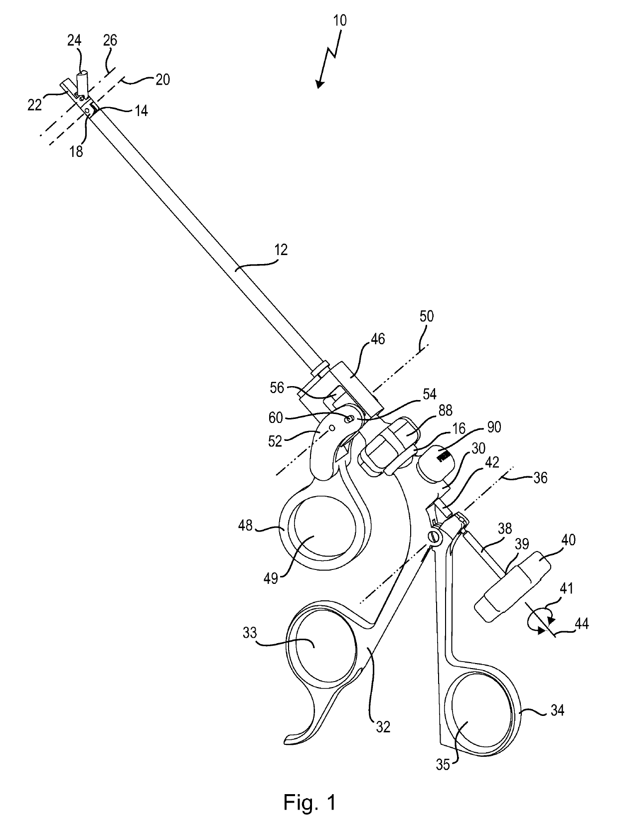
[0070]A medical instrument shown in FIG. 1 is designated in its entirety by reference number 10.

[0071]The instrument 10 has an elongate, stiff hollow shaft 12, which has a distal end 14 and a proximal end 16.

[0072]A jaw head 18 is secured on the distal end 14.

[0073]The jaw head 18 is arranged on the distal end 14 so as to be pivotable about a first axis 20, which extends transversely with respect to a longitudinal axis 44 of the shaft 12.

[0074]The jaw head 18 has a stationary jaw part 22 and a pivotable jaw part 24.

[0075]The pivotable jaw part 24 is arranged on the jaw head 18 so as to be pivotable about a second axis 26.

[0076]The second axis 26 extends parallel to the first axis 20 and lies distally in front of the first axis 20.

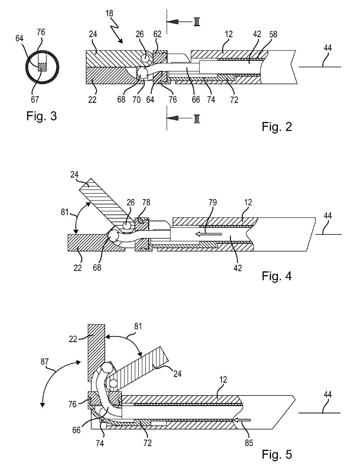
[0077]As is explained in more detail below in connection with FIGS. 2 to 5, the entire jaw head 18 is pivotable about the first axis 20, in particular by about 90°, and, in each of these pivot positions, the pivotable jaw part 24 is pivotable about the seco...


PUM


Abstract

A medical instrument has a shaft, which has a distal end and a proximal end, with a jaw head which is arranged at the distal end and is pivotable out from the longitudinal axis of the shaft, wherein the jaw head has two jaw parts, of which at least one is pivotable, furthermore, with a first actuation element for pivoting the jaw head, and with a second actuation element for pivoting the pivotable jaw part, wherein the actuation elements are received in the shaft, and with control elements which are arranged at the proximal end of the shaft and are used for controlling the movement of the actuation elements. The actuation elements are arranged extending coaxially with respect to each other, and that the actuation elements are received in the shaft so as to be rotatable jointly about the shaft axis and to be rotatable relative to the shaft.

Description

FIELD OF THE INVENTION[0001]The invention relates to a medical instrument with a shaft, which has a distal end and a proximal end, with a jaw head which is arranged at the distal end and is pivotable out from the longitudinal axis of the shaft.BACKGROUND OF THE INVENTION[0002]A medical instrument of this kind is known from DE 93 02 650 U1.[0003]The known medical instrument is designed in the form of medical forceps. A jaw head is arranged at the distal end of an elongate rigid shaft and is pivotable out from the longitudinal axis of the shaft. The jaw head has a rigid jaw part and a pivotable jaw part.[0004]To pivot the jaw head, the latter is connected to a first actuation element in the form of a wire, which is guided all the way through the shaft to the proximal end. There, the wire is connected to a movable grip part of a scissor-like handle. This movable grip part represents a control element by which this wire can be moved axially to and fro in the shaft in order to pivot the ...

Claims


Application Information

Patent Timeline
Patent Type & Authority Patents(United States)
IPC IPC(8): A61B17/29A61B17/28A61B17/00
CPCA61B17/282A61B17/29A61B2017/2929A61B2017/294A61B2017/2927A61B2017/00398A61B17/2804A61B2017/2926A61B2017/2947A61B2017/2939
Inventor FRINGS, HERMANN-JOSEF
Owner KARL STORZ GMBH & CO KG
Learn More