Tread comprising voids for civil engineering vehicle tire

Active Publication Date: 2017-04-06
MICHELIN & CO CIE GEN DES ESTAB MICHELIN +1
View PDF12 Cites 1 Cited by
  • Summary
  • Abstract
  • Description
  • Claims
  • Application Information

AI Technical Summary

Benefits of technology

The patent text discusses ways to improve the performance of tires in terms of cornering grip and traction / braking. One way is to have a certain level of wear on the tire, which can change the orientation and ratios of the major and minor axes, making it easier to achieve good performance in the rear axle. Additionally, the text suggests that molding the cavities in the tire with a relief angle can help prevent foreign objects from getting inside the cavities and affecting performance. Overall, the patent aims to provide a tire design that can improve its performance over time and with wear.

Problems solved by technology

The working of mines requires recourse to the use of suitable vehicles notably able to carry very heavy loads of the materials processed in these mines, covering longer or shorter distances over ground with some degree of slope and often covered with bodies that may impair grip performance either in terms of traction or in terms of braking or even in terms of steering.
The constraints on the use of the vehicles are such that it is common practice to fit new tires to the front axle of such vehicles and remove them and fit them to the rear axle in order to finish wearing away their tread.

Method used


Image

  • Tread comprising voids for civil engineering vehicle tire
  • Tread comprising voids for civil engineering vehicle tire

Examples


Embodiment Construction

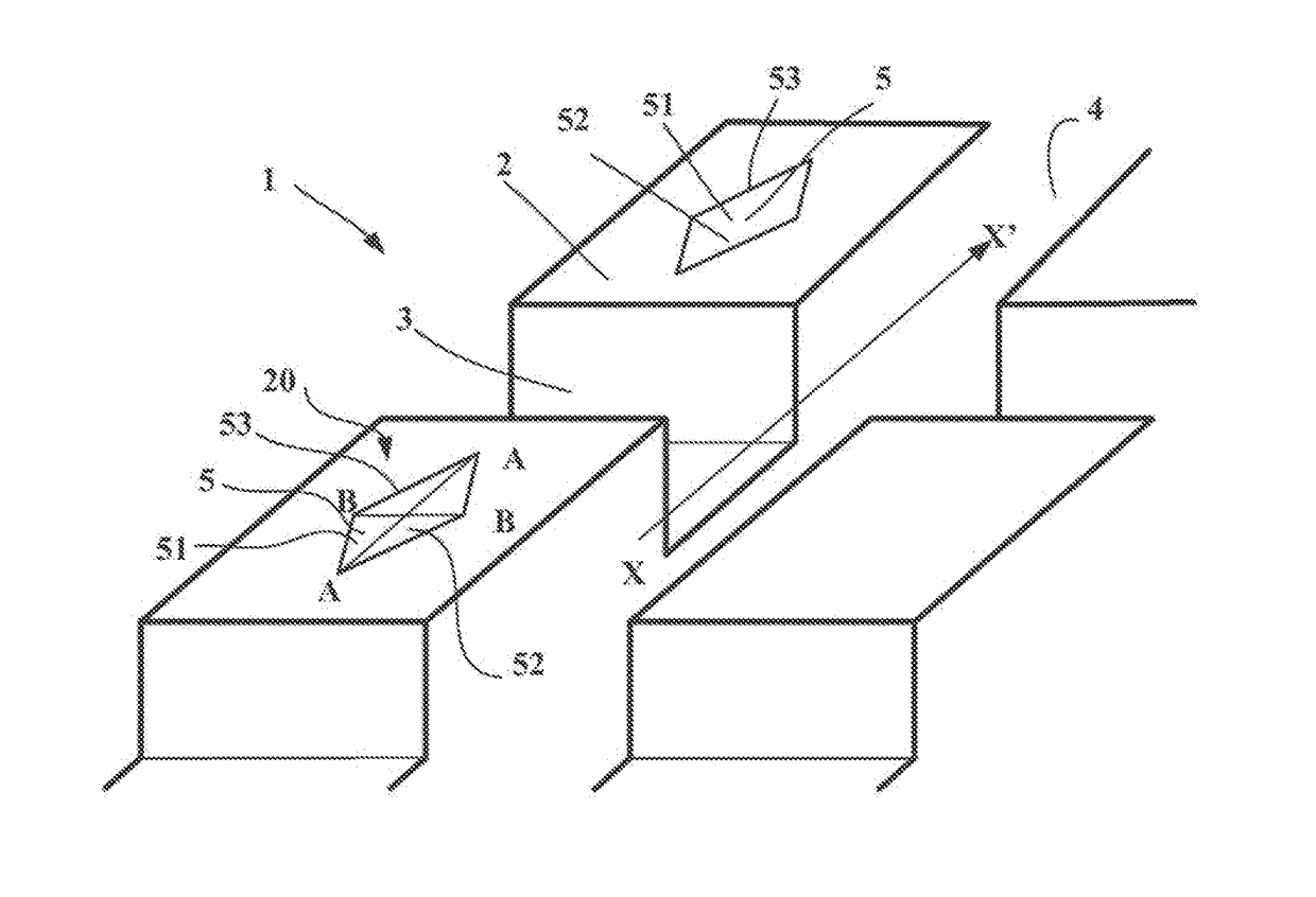
[0039]FIG. 1 depicts a partial view of an alternative form of tread pattern for a tread 1 according to the disclosure, this tread 1 being depicted as new, namely prior to any running.

[0040]In this FIG. 1 it is possible to distinguish a part forming a shoulder of the tread, this part being made up of a plurality of blocks 2 delimited by transverse grooves 3 intersecting a groove 4 that runs circumferentially. These transverse and circumferential grooves have the same depth corresponding substantially to the thickness EMU of material to be worn away during running. In this particular instance, the depth of the grooves is equal to 100 mm.

[0041]In this figure, the circumferential direction is embodied by an arrow XX′ extending along the circumferential groove.

[0042]Each block 2 of the shoulder part comprises lateral faces and a contact face 20 intended to come into contact with the ground during running. The intersections between the contact face 20 and the lateral faces in this instanc...


PUM


Abstract

The tread has a wearable thickness of material EMU and has raised elements delimited by grooves. Each solid part has a contact face and a cavity with a depth greater than 50% of the wearable thickness. Each cavity opens onto the contact face when new and is delimited by a wall surface and a bottom surface. Each wall surface deliminates a cavity that intersects the contact face along a corner edge contour that has a geometry that has a major axis which is at least 1.5 times the length of a minor axis when new. For any tread surface down to a predefined wear level, the level is at most 30% of the wearable thickness of material EMU, and the angle between the major axis and the circumferential direction is between 0 and 40 degrees. After the wear level, the angle is greater than 40 degrees.

Description

CROSS-REFERENCE TO RELATED APPLICATION[0001]The present invention claims priority to PCT International Patent Application Serial No. PCT / EP2015 / 055474 filed Mar. 16, 2015 entitled “Tread Comprising Voids For Civil Engineering Vehicle Tire,” which claims the benefit of FR Patent Application Serial No. 1452242 filed Mar. 18, 2014, the entire disclosures of the applications being considered part of the disclosure of this application and hereby incorporated by reference.BACKGROUND OF THE INVENTION[0002]1. Field of the Invention[0003]The present disclosure relates to a tire tread for a civil engineering vehicle such as a dumper and more particularly to certain elements of the tread pattern of such a tread.[0004]2. Related Art[0005]The working of mines requires recourse to the use of suitable vehicles notably able to carry very heavy loads of the materials processed in these mines, covering longer or shorter distances over ground with some degree of slope and often covered with bodies tha...

Claims


Application Information

Patent Timeline
IPC IPC(8): B60C11/24B60C11/03B60C11/11
CPCB60C11/24B60C2200/065B60C11/032B60C11/11
Inventor NUGIER, FRANCKCHAUVIN, DOMINIQUELARREGAIN, ARNAUD
Owner MICHELIN & CO CIE GEN DES ESTAB MICHELIN
Why Eureka
Try Eureka