Windage shield system and method of suppressing resonant acoustic noise

a shield system and acoustic noise technology, applied in the field of windage shield systems and methods of suppressing resonant acoustic noise, can solve the problems of many modern commercial turbofans generating heat and noise between

Active Publication Date: 2017-04-06
GENERAL ELECTRIC CO
View PDF11 Cites 1 Cited by
  • Summary
  • Abstract
  • Description
  • Claims
  • Application Information

AI Technical Summary

Benefits of technology

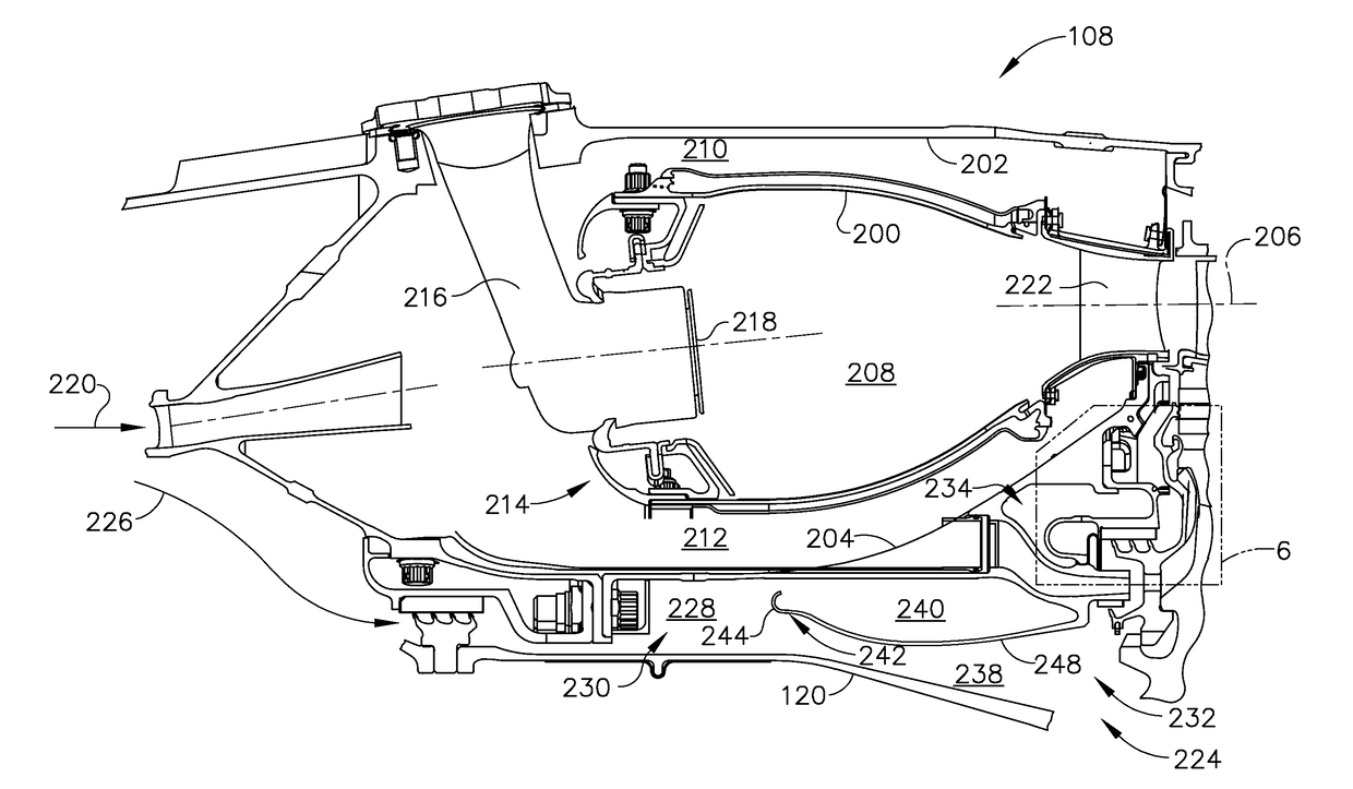
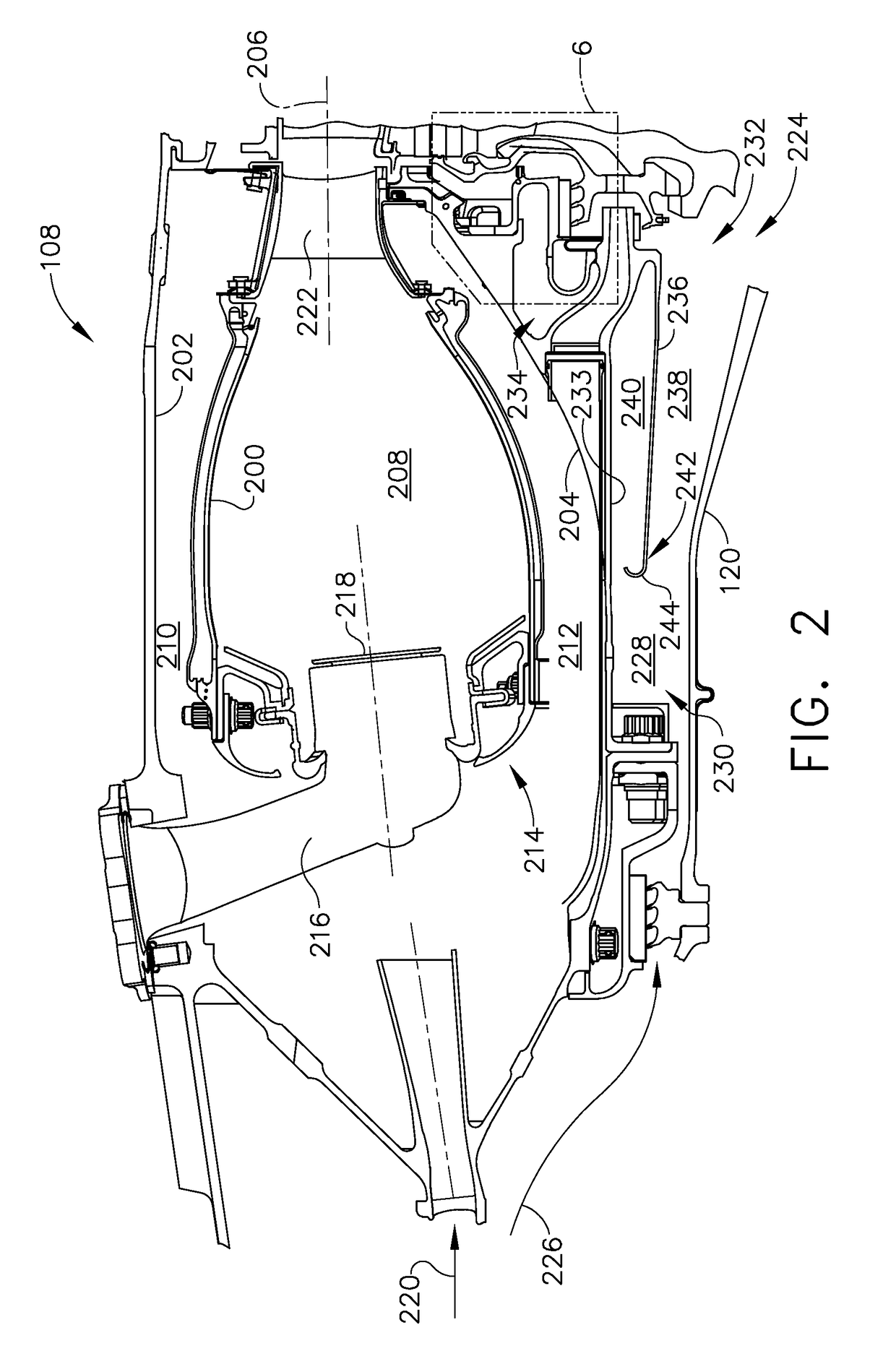
[0004]In one aspect, a windage shield system is provided. The system includes an annular cavity having an inlet end and an outlet end. The annular cavity is configured to direct a flow of cooling fluid from the inlet end to the outlet end. The system also includes a source of a flow of cooling fluid coupled in flow communication with the annular cavity. The annular cavity is bounded by a stationary component and a rotating component, and the rotating component introduces heat into the annular cavity by windage effects. The system also includes a cooling channel coupled in flow communication with the outlet end, and a first windage shield extending from the outlet end towards the inlet end within the annular cavity. The first windage shield divides the annular cavity into at least two flow paths, such as a first flow path defined between the rotating component and the first windage shield, and a second flow path defined between the stationary component and the first windage shield. The cooling channel is coupled in flow communication with the second flow path, such that a temperature of the second flow path is less than a temperature of the first flow path due to windage effects.
[0005]In another aspect, a windage shield system is provided. The system includes a cooling channel configured to channel a flow of cooling fluid therethrough, wherein the cooling channel is at least partially bounded by a first stationary component and a second stationary component. The system also includes an annular cavity positioned within the cooling channel. The annular cavity is bounded by the second stationary component and a rotating component, and the rotating component introduces heat into the annular cavity by windage effects. The system also includes a windage shield extending between the second stationary component and the rotating component such that the heat generated by the rotating component is restricted from being transferred towards the second stationary component through the windage shield.

Problems solved by technology

During operation, many modern commercial turbofans generate heat and noise between the surfaces of rotating members of the turbofan and the air surrounding the rotating members.

Method used


Image

  • Windage shield system and method of suppressing resonant acoustic noise
  • Windage shield system and method of suppressing resonant acoustic noise
  • Windage shield system and method of suppressing resonant acoustic noise

Examples


Embodiment Construction

[0015]In the following specification and the claims, reference will be made to a number of terms, which shall be defined to have the following meanings

[0016]The singular forms “a”, “an”, and “the” include plural references unless the context clearly dictates otherwise.

[0017]“Optional” or “optionally” means that the subsequently described event or circumstance may or may not occur, and that the description includes instances where the event occurs and instances where it does not.

[0018]Approximating language, as used herein throughout the specification and claims, may be applied to modify any quantitative representation that could permissibly vary without resulting in a change in the basic function to which it is related. Accordingly, a value modified by a term or terms, such as “about”, “approximately”, and “substantially”, are not to be limited to the precise value specified. In at least some instances, the approximating language may correspond to the precision of an instrument for ...


PUM


Abstract

A windage shield system is provided. The system includes an annular cavity having an inlet end and an outlet end. The annular cavity is configured to direct a flow of cooling fluid from the inlet end to the outlet end. The system also includes a source of a flow of cooling fluid coupled in flow communication with the annular cavity. The annular cavity is bounded by a stationary component and a rotating component, and the rotating component introduces heat into the annular cavity by windage effects. The system also includes a cooling channel coupled in flow communication with the outlet end, and a first windage shield extending from the outlet end towards the inlet end within the annular cavity.

Description

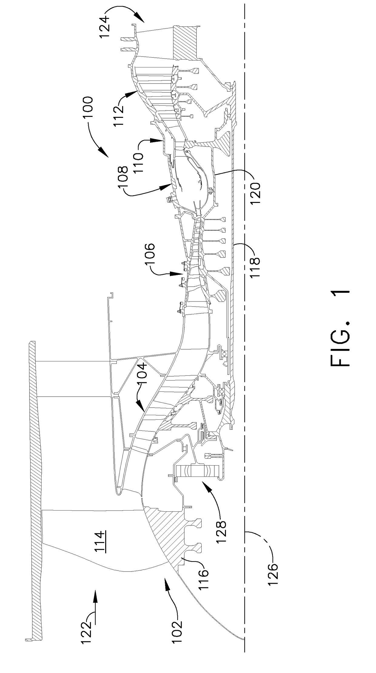
BACKGROUND[0001]The field of the disclosure relates generally to turbofan engines and, more particularly, to systems and methods of reducing the temperature of air in the rotor cavity of a turbine assembly.[0002]At least some known gas turbine engines, such as turbofan engines, include a fan, a core engine, and a power turbine. The core engine includes at least one compressor, a combustor, and a high-pressure turbine coupled together in a serial flow relationship. More specifically, the compressor and high-pressure turbine are coupled through a first drive shaft to form a high-pressure rotor assembly. Air entering the core engine is mixed with fuel and ignited to form a high energy gas stream. The high energy gas stream flows through the high-pressure turbine to rotatably drive the high-pressure turbine such that the shaft rotatably drives the compressor. The gas stream expands as it flows through a power or low-pressure turbine positioned aft of the high-pressure turbine. The low-p...

Claims


Application Information

Patent Timeline
Patent Type & Authority Applications(United States)
IPC IPC(8): F02C7/18F02C7/24F01D25/24F01D25/12
CPCF02C7/185F01D25/12F05D2260/972F01D25/243F02C7/24F01D5/082F05D2260/97
Inventor MUELLER, JOHN HERMANKLASING, KEVIN SAMUELGEBBIA, ANDREW B.
Owner GENERAL ELECTRIC CO
Why Eureka
Try Eureka