Light-modulating element and smart glass

a technology of light-modulating elements and smart glass, which is applied in the direction of static indicating devices, instruments, non-linear optics, etc., can solve the problems of insufficient acquisition of light-modulating functions, deterioration of visibility through glass, and inability to achieve light-modulating functions that protect the light-modulating function. , to achieve the effect of effective adjustment and control of the transmission sta

Active Publication Date: 2017-04-06
TIANMA MICRO ELECTRONICS CO LTD
View PDF4 Cites 28 Cited by
  • Summary
  • Abstract
  • Description
  • Claims
  • Application Information

AI Technical Summary

Benefits of technology

[0020]As described above, the present invention is designed to include: in opposition to one another, the first transparent substrate on which the first transparent electrode and a plurality of light transmissive regions isolated from each other are provided and the second transparent substrate on which two kinds of transparent electrodes are provided; and the electrophoretic member disposed in the gap formed therebetween. This makes it possible to provide in particular the light-modulating element that is capable of effectively adjusting and controlling the transmission state of the transmission light in accordance with the demand and the changes in the use environment and provide the smart glass on which the same is loaded.

Problems solved by technology

Especially in the light-shielding state, the entire surface of the glass is equally light-shielded so that the visibility through the glass becomes deteriorated.
Further, when the optical density at the time of shielding the light is set to be low in order to minimize the deterioration in the visibility in the light-shielding state, the light-shielding effect by the light-modulating function cannot be acquired sufficiently.
That is, the entire surface of the substrate cannot be light-shielded, so that the complete light-shielding characteristic cannot be secured.

Method used


Image

  • Light-modulating element and smart glass
  • Light-modulating element and smart glass
  • Light-modulating element and smart glass

Examples


first embodiment

[0059]A first embodiment of a light-modulating element according to the present invention will be described by referring to FIG. 1 to FIG. 19.

(Basic Structures)

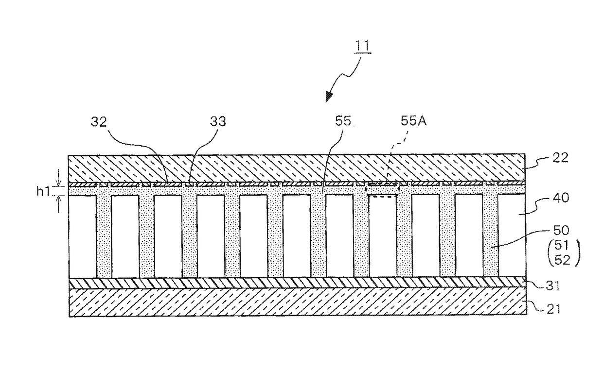
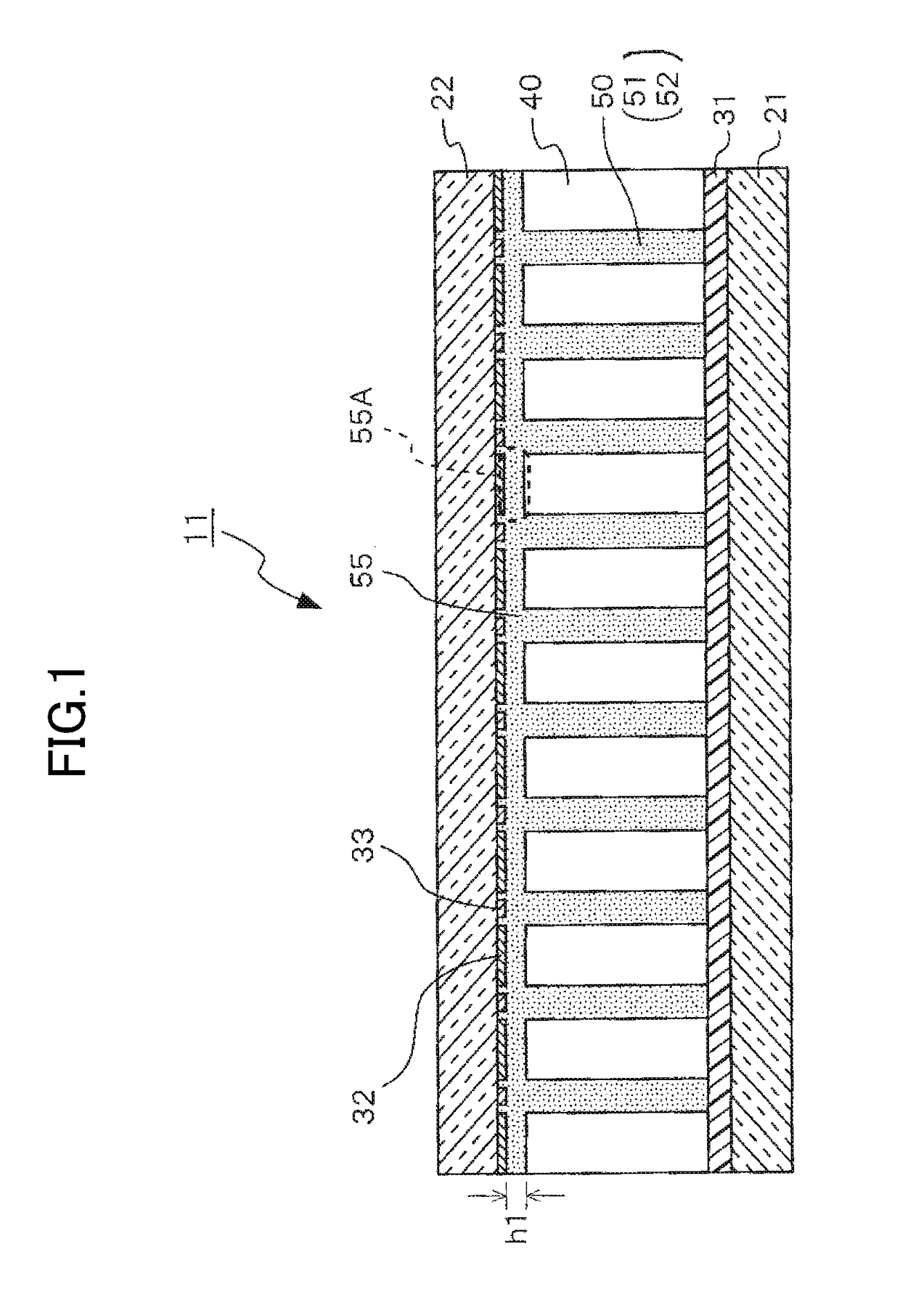
[0060]As shown in FIG. 1, a light-modulating element 11 according to the first embodiment includes: a first transparent substrate 21; a first transparent electrode 31 formed on the surface of the first transparent substrate 21; a plurality of light transmissive regions 40 formed to be isolated from each other on the surface of the first transparent electrode 31; a second transparent substrate 22 counter-disposed on the upper side of the light transmissive region 40 by sandwiching an air gap 55A on each of the light transmissive regions 40; a plurality of second transparent electrodes 32 disposed on the second transparent substrate 22 at positions corresponding to each of the light transmissive regions 40; a plurality of third transparent electrodes 33 disposed between each of the second transparent electrodes 32; and an elect...

second embodiment

[0145]A second embodiment of the light-modulating element according to the present invention will be described by referring to FIG. 20. Same reference numerals are to be used for the structural members equivalent to those of the first embodiment described above, and explanations thereof are omitted.

[0146]As shown in FIG. 20, a light-modulating element 12 according to the second embodiment has a feature in respect that there is a first interlayer insulating film (an on-first-electrode insulating film) 61 disposed between the first transparent electrode 31 and the light transmissive regions 40. In this respect, it is different from the first embodiment described above.

[0147]The film thickness of the first interlayer insulating film 61 is preferable to fall within a range of 10 nm to 1000 nm. In the second embodiment, it is formed to have the film thickness of 100 nm.

[0148]As the structural material of the first interlayer insulating film 61, it is possible to use a silicon oxide film,...

third embodiment

[0151]A third embodiment of the light-modulating element according to the present invention will be described by referring to FIG. 31. Same reference numerals are to be used for the structural members equivalent to those of the second embodiment described above, and explanations thereof are omitted.

[0152]As shown in FIG. 31, a light-modulating element 16 according to the third embodiment has a feature in respect that there is a fourth interlayer insulating film (an on-second-and-third-electrodes insulating film) 64 disposed on the surfaces of the second transparent electrodes 32 and the third transparent electrodes 33 in addition to the first interlayer insulating film (the on-first-electrode insulating film) 61 disposed between the first transparent electrode 31 and the light transmissive regions 40. In this respect, it is different from the second embodiment described above.

[0153]The film thickness of the fourth interlayer insulating film 64 is preferable to fall within a range of...


PUM

PropertyMeasurementUnit
thicknessaaaaaaaaaa
thicknessaaaaaaaaaa
heightaaaaaaaaaa

Abstract

A light-modulating element comprises: first and second transparent substrates arranged in opposition to one another; a first transparent electrode arranged on the opposition surface of the first transparent substrate; a plurality of light transmissive regions arranged between the first transparent electrode and the second transparent substrate so as to be separated from one another; a plurality of second transparent electrodes arranged at respective positions on the second transparent substrate opposing the respective light transmissive regions, and that are arranged so as to be separated by a given distance from the respective light transmissive regions; a plurality of third transparent electrodes arranged individually between the second transparent electrodes at a predetermined distance therefrom on the second transparent substrate side; and an electrophoretic member arranged within a gap formed between the first transparent substrate and the second transparent substrate, and that includes light-shielding electrophoretic particles.

Description

TECHNICAL FIELD[0001]The present invention relates to a light-modulating element which controls the emission state of transmitted light and to a smart glass to which the same is loaded.BACKGROUND ART[0002]Recently, due to an increase in the awareness about ecology, there is an increasing demand for a smart glass with a built-in light-modulating function which modulates the light shining into the inside of rooms and the like.[0003]For the smart glass contributing to improving the air-conditioning energy efficiency, an electrochromic element exhibiting a function of switching a transparent state and a light-shielding state (nontransparent state) is used. Through controlling the influence of natural light to decrease the air-conditioning load by the light-modulating function regarding the switching of the states, the electric power use amount is reduced.[0004]As an example of the practical use of the glass to which the electrochromic element is built-in, the technical content disclosed...

Claims


Application Information

Patent Timeline
Patent Type & Authority Applications(United States)
IPC IPC(8): G02F1/167G02F1/1335G02F1/133G02F1/1333G02F1/1339G02F1/16756G02F1/16762G02F1/1679
CPCG02F1/167G02F1/133345G02F1/1339G02F2203/48G02F1/133512G02F2001/1676G02F2203/01G02F1/13306G02F1/1679G02F1/16762G02F1/16756
Inventor SHIOTA, KUNIHIRO
Owner TIANMA MICRO ELECTRONICS CO LTD
Why Eureka
Try Eureka