Illumination ceiling lamp and lame cap thereof

Inactive Publication Date: 2017-04-27
DONGGUAN BRIGHT YIN HUEY LIGHTING CO LTD
View PDF5 Cites 2 Cited by
  • Summary
  • Abstract
  • Description
  • Claims
  • Application Information

AI Technical Summary

Benefits of technology

[0014]Compared with the prior art, the illumination ceiling lamp of the present patent is provided with the lampshade, the lamp cap and the snap rings, wherein the lampshade is sleeved on the lamp cap, and the snap rings are connected to the lamp cap by threads and configured to limit the lampshade. This illumination ceiling lam

Problems solved by technology

In the prior art, when an illumination ceiling lamp is in use, a lamp cap portion thereof is generally exposed in air, it is inevitable to cause dust accumulation outside the lamp cap as time goes on, thereby affecting normal glowing and brightening of the lamp cap, and therefore, more illumination ceiling lamps with lamp caps and lampshades arise in the market.
Because the lamp cap is connected to the lampshade in a non-detachable manner, it is very inconvenient to disassem

Method used


Image

  • Illumination ceiling lamp and lame cap thereof
  • Illumination ceiling lamp and lame cap thereof
  • Illumination ceiling lamp and lame cap thereof

Examples


Example

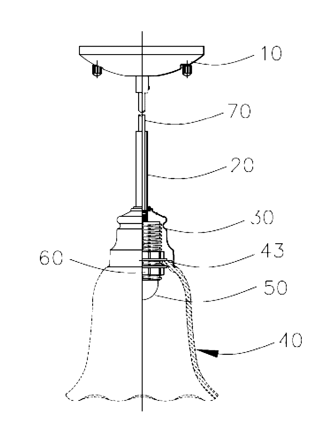
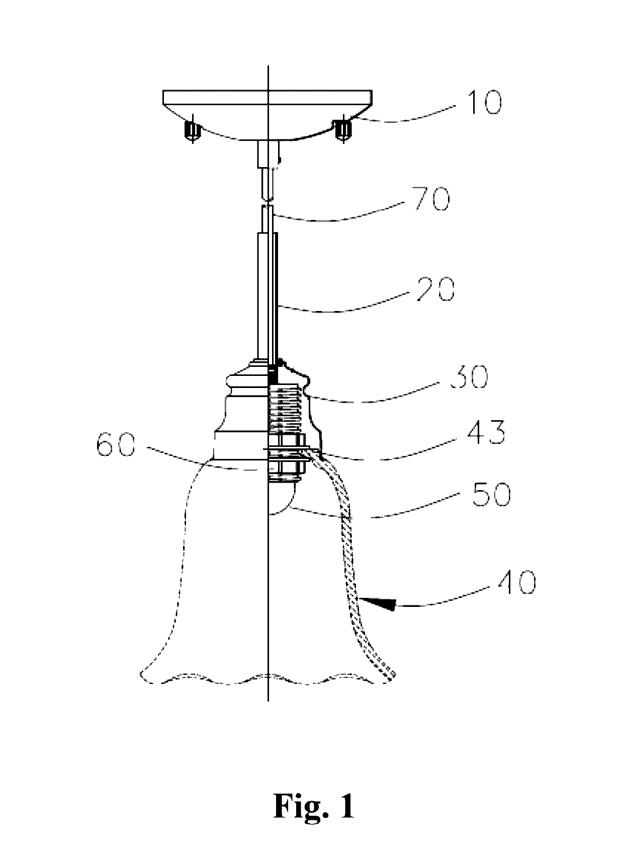
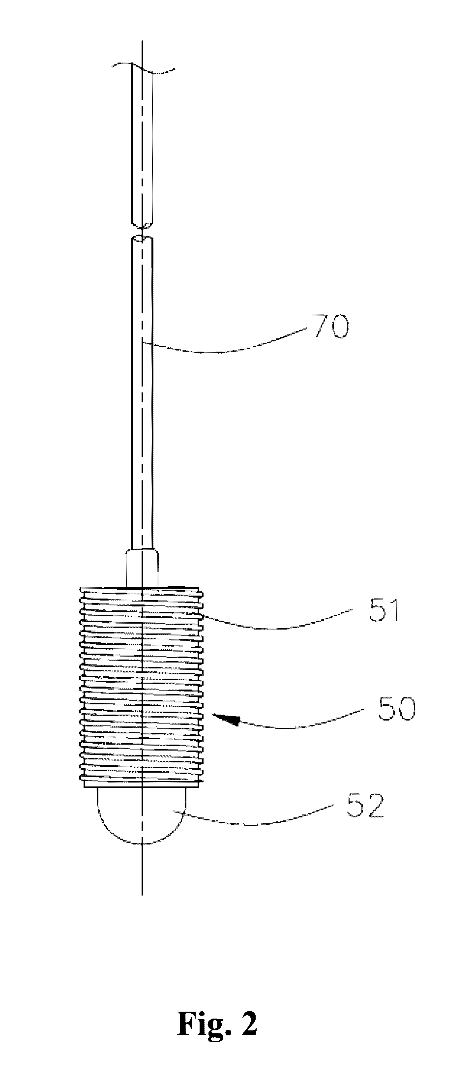
[0024]FIGS. 1-4 illustrate the embodiment 1 in the illumination ceiling lamp of the present patent. The illumination ceiling lamp comprises a mounting base 10, a boom 20, a lamp cap cover 30, a lampshade 40, a lamp cap 50, snap rings 60 and a power wire 70, wherein the lower end of the boom 20 is assembled on the lamp cap cover 30, the upper end of the boom 20 is fixed to the mounting base 10, the power wire 70 penetrates into the boom 20, and the lower end of the power wire 70 is connected to the lamp cap 50. The upper end of the power wire 70 penetrates through the lamp cap cover 30 and is connected into the mounting base 10. The snap rings 60 are connected to the lamp cap 50 and are configured to limit the lamp cap 40, and the lampshade 40 covers the lamp cap 50.

[0025]The lampshade 40 is designed in a horn shape, one end thereof being an open end of the horn, and the other end thereof being provided with a limiting portion 41. The limiting portion 41 is provided with a mounting h...


PUM


Abstract

The illumination ceiling lamp comprises a mounting base, the lamp cap, a lamp cap cover, a lampshade, snap rings and a power wire, wherein the lower end of the power wire is connected to the lamp cap; the upper end of the power wire penetrates through the lamp cap cover and is connected into the mounting base; the snap rings are connected to the lamp cap by threads; the lampshade covers the lamp cap; and the snap rings are configured to limit the lampshade. The lamp cap comprises a lamp holder and an illumination lamp, wherein the illumination lamp is arranged on one end surface of the lamp holder; the lamp holder is cylindrical; the outside surface of the lamp holder is provided with outer threads in a raised manner; the other end surface of the lamp holder is provided with a mounting hole into which the power wire penetrates.

Description

FIELD OF THE INVENTION[0001]The present patent relates to a lamp, in particular to an illumination ceiling lamp convenient to mount and a lamp cap thereof.BACKGROUND OF THE INVENTION[0002]In the prior art, when an illumination ceiling lamp is in use, a lamp cap portion thereof is generally exposed in air, it is inevitable to cause dust accumulation outside the lamp cap as time goes on, thereby affecting normal glowing and brightening of the lamp cap, and therefore, more illumination ceiling lamps with lamp caps and lampshades arise in the market. The upper end of the lampshade is fixedly connected to the lamp cap of the illumination ceiling lamp by snap rings, and the lamp cap portion of the illumination ceiling lamp is positioned in the glass lampshade. Because the lamp cap is connected to the lampshade in a non-detachable manner, it is very inconvenient to disassemble, assemble ad clean the lamp cap and the lampshade. If the lamp cap and the lampshade are disassembled forcedly, th...

Claims


Application Information

Patent Timeline
IPC IPC(8): F21V17/16F21V23/00F21S8/06
CPCF21V17/16F21V1/00F21V23/002F21S8/063
Inventor XU, SHUISHENG
Owner DONGGUAN BRIGHT YIN HUEY LIGHTING CO LTD
Why Eureka
Try Eureka