

Load switch
A load switch and crossbeam technology, applied in the field of load switches, can solve the problems of heavy load switch, inconvenient disassembly and assembly, high temperature difference, etc., and achieve the effect of good insulation performance, convenient disassembly and assembly, and improved strength
- Summary
- Abstract
- Description
- Claims
- Application Information
AI Technical Summary
Problems solved by technology
Method used
Image

Examples
Embodiment Construction
[0028] The present invention will be further described now in conjunction with accompanying drawing. These drawings are simplified schematic diagrams only to illustrate the basic structure of the present invention in a schematic way, so they only show the components relevant to the present invention.
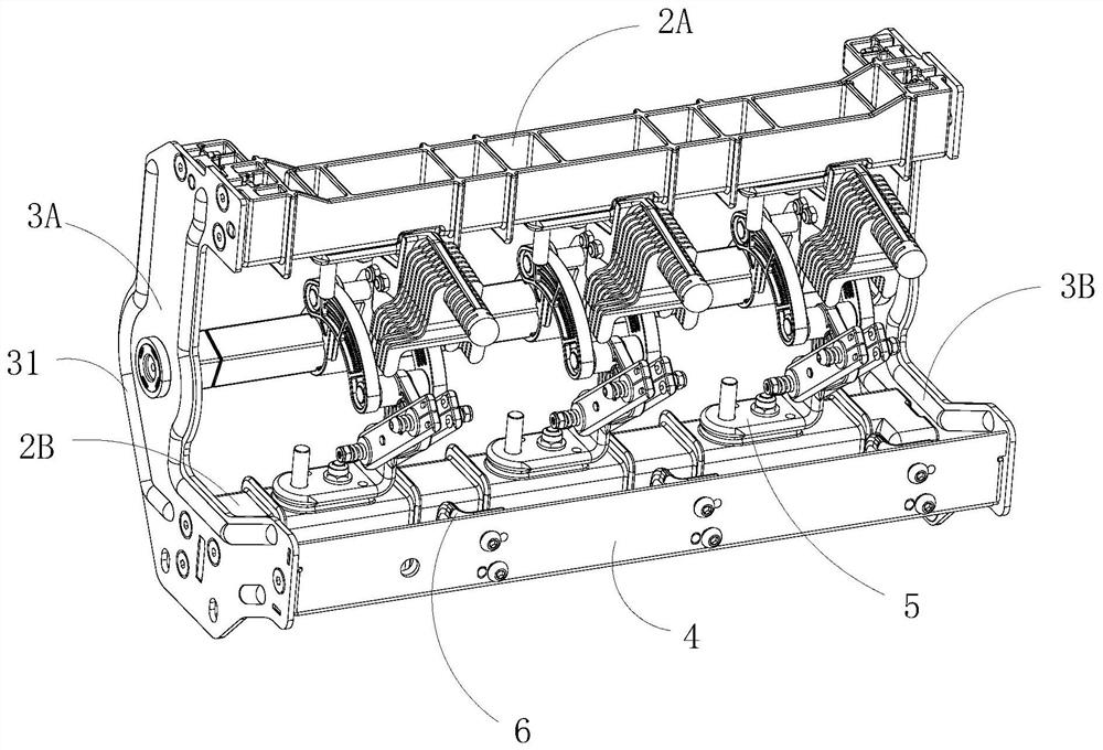
[0029] Such as Figure 1 to Figure 3 As shown, a load switch includes a rear bulkhead 3A, a front bulkhead 3B, an upper beam 2A, a lower beam 2B, a grounding static contact seat mounting plate 4 and a rotating shaft;
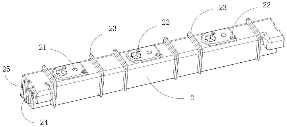
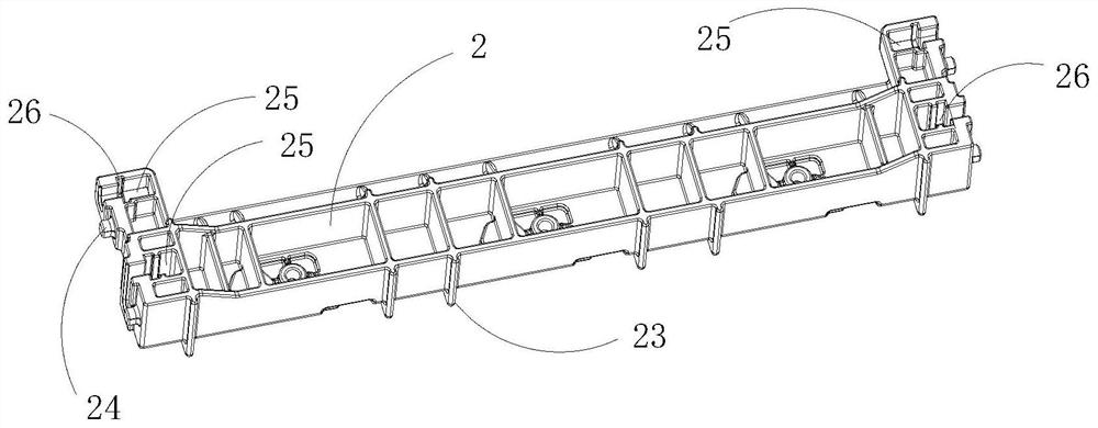
[0030] Both the upper beam 2A and the lower beam 2B are made of insulating materials;
[0031] The rear bulkhead 3A is fastened with bolts to the front side of the upper beam 2A, the lower beam 2B and the grounding static contact seat mounting plate 4;
[0032] The front bulkhead 3B is fastened with bolts to the rear side of the upper beam 2A, the lower beam 2B and the grounding static contact seat mounting plate 4 .
[0033] Both the upper beam 2A and the lowe...
PUM
 Abstract
Description
Claims
Application Information