Inner and outer wing butt joint structure for small unmanned aerial vehicle

A small unmanned aerial vehicle, connecting nut technology, applied in the directions of wings, fuselage, aircraft parts, etc., can solve the complex structure of the docking structure of the inner and outer wings of the drone, the high cost of production, processing and assembly of parts, and the inability to realize the inner and outer wings. Frequent disassembly and other problems, to achieve the effect of simple assembly and disassembly, high reliability and safety, and simple structure

Inactive Publication Date: 2019-05-28
CHENGDU AIRCRAFT INDUSTRY GROUP
View PDF11 Cites 2 Cited by
  • Summary
  • Abstract
  • Description
  • Claims
  • Application Information

AI Technical Summary

Problems solved by technology

[0004] However, the docking structure of the inner and outer wings of the above-mentioned UAV is complex, the cost of production, processing and assembly of parts is high, and the frequent disassembly of the inner and outer wings cannot be realized, which increases the difficulty of transportation and maintenance.

Method used


Image

  • Inner and outer wing butt joint structure for small unmanned aerial vehicle
  • Inner and outer wing butt joint structure for small unmanned aerial vehicle

Examples


Embodiment 1

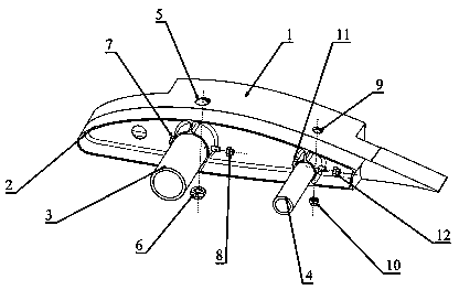
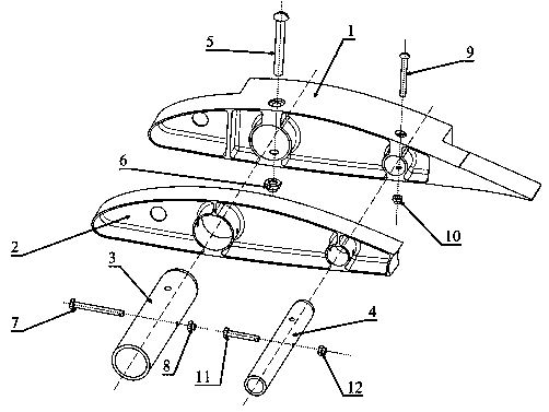
[0021] An inner and outer wing docking structure for a small unmanned aerial vehicle includes an inner wing metal butt joint rib 1 and an outer wing metal joint rib 2. There are two cylindrical grooves with one end closed on the inner wing metal joint rib 1, and the outer wing metal joint There are penetrating round holes of the same size at the corresponding positions on the butt rib 2, and the front sleeve metal tube 3 and the rear sleeve metal tube 4 pass through the round holes at the corresponding positions on the metal joint rib 2 of the outer wing, and fit into the metal joint of the inner wing. Closed cylindrical groove at corresponding position at butt rib 1.

[0022] The front socketed metal pipe 3 is connected to the metal butt joint rib 1 of the inner wing through the front metal pipe vertical connection bolt 5 and the front metal pipe vertical connection nut 6, and the front metal pipe course connection bolt 7 and the front metal pipe course connection nut 8 links...

Embodiment 2

[0028] In this structure, the inner wing metal butt joint rib 1 contains two cylindrical grooves with one end closed, and the outer wing metal butt joint rib 2 has a penetrating round hole of the same size at the corresponding position, and the front sleeve metal pipe 3 and the rear sleeve joint The metal tube 4 runs through the circular hole at the corresponding position on the metal butt joint rib 2 of the outer wing, and fits into the closed cylindrical groove at the corresponding position at the metal butt joint rib 1 of the inner wing. The front sleeve metal pipe 3 is connected to the inner wing metal butt joint rib 1 through the front metal pipe vertical connection bolt 5 and the front metal pipe vertical connection nut 6, and is connected to the inner wing metal butt joint rib 1 through the front metal pipe course connection bolt 7 and the front metal pipe course connection nut 8. The outer wing metal butt joint rib 2 is connected; the rear sleeve metal pipe 4 is connect...


PUM


Abstract

The invention belongs to the technical field of airplane design and particularly relates to an inner and outer wing butt joint structure for a small unmanned aerial vehicle, which can realize butt joint of an inner wing and an outer wing of the small unmanned aerial vehicle. The inner and outer wing butt joint structure for the small unmanned aerial vehicle comprises an inner wing metal butt jointrib and an outer wing metal butt joint rib; two cylindrical grooves are formed in the inner wing metal butt joint rib; one end of each cylindrical groove is closed; run-through round holes with the same size are formed in the corresponding position of the outer wing metal butt joint rib; and a front sleeving metal pipe and a back sleeving metal pipe run through the round holes in the corresponding position of the outer wing metal butt joint rib and sleeve the closed cylindrical grooves at the corresponding position of the inner wing metal butt joint rib. The inner and outer wing butt joint structure has the characteristics of high load transfer efficiency, simple structure form, high reliability and safety and simplicity in assembling and disassembling mode, and can meet the customer requirements.

Description

technical field [0001] The application belongs to the technical field of aircraft design, and in particular relates to an inner and outer wing docking structure for a small unmanned aerial vehicle for realizing the purpose of docking the inner and outer wings of a small unmanned aerial vehicle. Background technique [0002] The competition in China's small UAV industry is fierce. The structural design work must not only ensure the structural strength and performance of the aircraft and realize the functional requirements required by customers, but also reduce the production and assembly costs of parts and components, and facilitate transportation and maintenance. Especially for the key structural parts of the UAV, on the premise of meeting the performance and requirements, optimizing the structural design scheme and reducing the difficulty of production, processing and assembly are the key factors to reduce the overall cost. For the airfoil structure form composed of inner w...

Claims


Application Information

Patent Timeline
Patent Type & Authority Applications(China)
IPC IPC(8): B64C3/00B64C1/26
Inventor 冯若琪唐克兵方雄王珏杨文冯玉龙
Owner CHENGDU AIRCRAFT INDUSTRY GROUP
Why Eureka
Try Eureka