Integrated Precise Photoelectric Sighting System

Active Publication Date: 2017-04-27
HUNTERCRAFT
View PDF0 Cites 9 Cited by
  • Summary
  • Abstract
  • Description
  • Claims
  • Application Information

AI Technical Summary

Benefits of technology

The present invention provides a precise photoelectric sighting system that allows for easy shooting calibration, quick and accurate sighting, man-machine interaction, two-eye sighting, switching of display modes, a three-dimension image effect, and target tracing. The system includes a housing with an integrated field-of-view obtaining unit, range-finding unit, display unit, three-dimension unit and sighting circuit unit. The system simplifies the calibration process by allowing the user to calibrate and shoot. The invention also provides a calibration method for accurate shooting during a shooting process of a photoelectric sighting system. The system allows for easy calibration and provides a real impact point for the user to align with the target. The precise photoelectric sighting system is also designed to allow for easy target tracing and enhances the accuracy of calibration through a second shooting calibration after the first.

Problems solved by technology

After long-term use, either the rotary knob or other mechanical adjustments will cause abrasive wear or offset to the machine, resulting in offset.
However, long-range shoot sighting is extremely demanding on preciseness.
In long-range shooting, a minor error in a gun or sight will cause great deviation in a shooting result.
This brings extreme inconvenience in practical application.
However, in practice, it is difficult for a non-professional person to highly focus on the display device or observe and trace the target for a long time.
In addition, observing and tracing the target without the gunsight or by using other devices causes great inconvenience for the shooter in the aspects of operation and shooting experience.
However, in the case of single-eye sighting, it is inconvenient for the user to watch what happens around.
Sudden change of the environment will inevitably affect the shooting.
It appears difficult for the conventional gunsight to search target and sight an object, usually after an object is finally sighted, it is difficult to be again sighted due to shaking or target movement.

Method used


Image

  • Integrated Precise Photoelectric Sighting System
  • Integrated Precise Photoelectric Sighting System
  • Integrated Precise Photoelectric Sighting System

Examples


Embodiment Construction

[0056]In order to make the objective, technical solution, and advantages of the present invention more elucidated, the present invention will be described in more detail with reference to the accompanying drawings and embodiments. It should be understood that the preferred embodiments described here are only for explaining the present invention, not for limiting the present invention.

[0057]On the contrary, the present invention covers any replacements, modifications, equivalent methods and solutions defined by the claims within the spirit and scope of the present invention. Further, in order to make the public understand better the present invention, some specific detailed portions are elaborated in the following depiction of the details of the present invention.

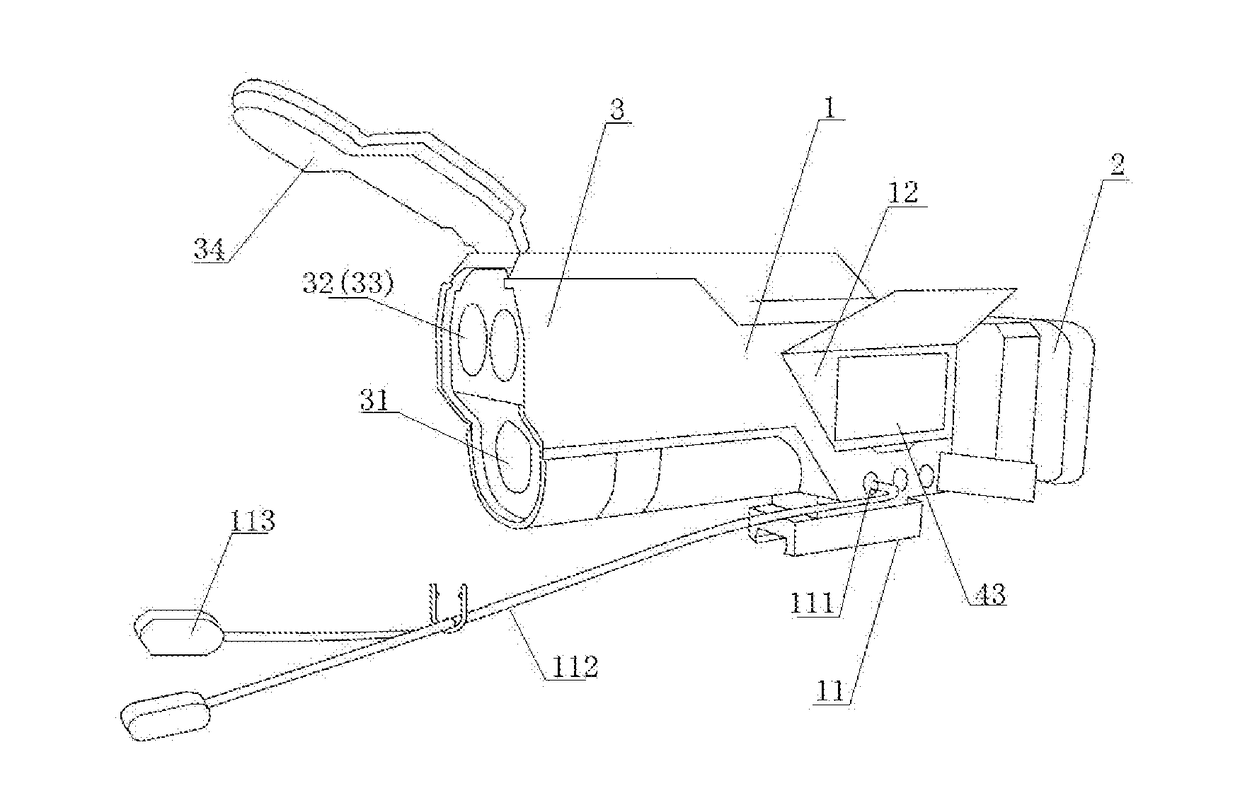
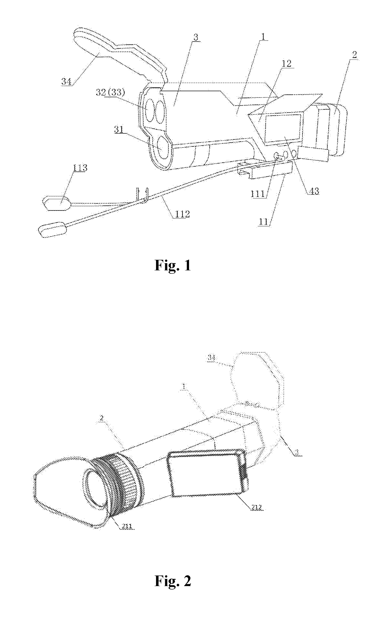
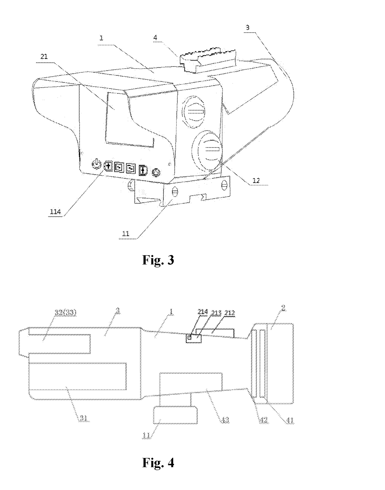
[0058]The present invention proposes an integrated precise electro-optic sighting system that facilitates calibration. The photoelectric sighting system may be mounted on various kinds of sporting guns, e.g., riffles, etc. T...


PUM


Abstract

The invention discloses an integrated precise photoelectric sighting system that facilitates calibration, the system comprises a field-of-view obtaining unit, a range-finding unit, a display unit, three-dimension unit and a sighting circuit unit; In the sighting system, an optical image obtained by the field-of-view obtaining unit can be displayed on the display unit, which simultaneously displays the optical image, an icon and a reticle, wherein the icon is used to indicate the adjustment of the optical image, and the reticle is used to aim the target in the optical image. The three-dimension unit can convert the reticle, the icon and the image information obtained by the field-of-view obtaining unit, which are displayed by the display unit, from a two-dimension image into a three-dimension image, thereby allowing user to perceive deeply the environment. The precise photoelectric sighting system applies the sighting circuit unit and the range-finding unit to perform precise prediction to the impact point.

Description

FIELD OF THE INVENTION[0001]The present invention relates to the technical field of gun sight, and more specifically relates to an integrated precise photoelectric sighting system that facilitates calibration.BACKGROUND OF THE INVENTION[0002]Traditional sights usually include mechanical sights and optical sights, wherein the mechanical sights generally refer to performing sighting mechanically through a metallic sight such as a rear sight, a front sight, and a notch; the optical sights refer to imaging with optical lens, where a target image and a line of sight are superimposed on a same focal plane, such that a point of sighting will not be affected even with slight eye offset.[0003]During a shooting process, the two traditional sights need to calibrate reticle and an impact point repeatedly so as to make the impact point in coincidence with a reticle center. During the process of calibrating the impact point in coincidence with the reticle center, it is required to tune a rotary k...

Claims


Application Information

Patent Timeline
IPC IPC(8): F41G3/16F41G1/54F41G1/38F41G3/08
CPCF41G3/165F41G1/38F41G1/54F41G3/08F41G1/32F41G1/473F41G3/06
Inventor ZHANG, LINSHI, CHUNHUASU, SANG
Owner HUNTERCRAFT
Why Eureka
Try Eureka