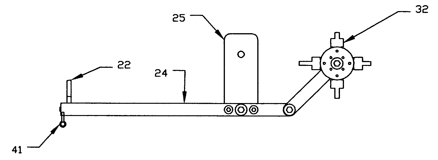
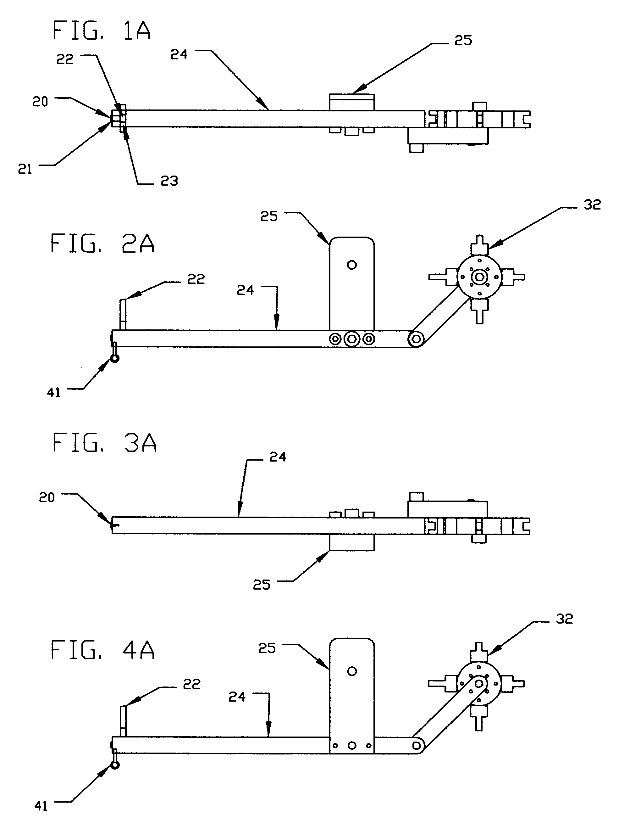
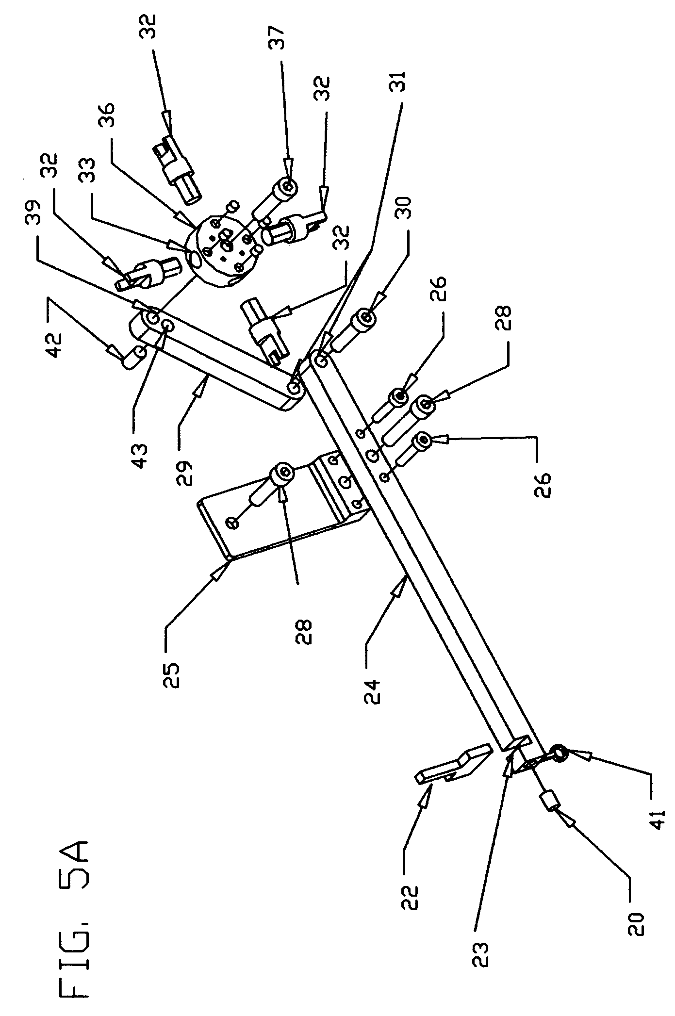
Wheel blade sight

a wheel blade and sight technology, applied in the field of bow sights, can solve the problems of pin sight on the rear, confusion of selecting ranges and obstructions of sight field, and etc., to achieve the effect of reducing the need for forearm guards and being more rigid

Inactive Publication Date: 2006-04-20
LACE CHARLES ROBERT
View PDF20 Cites 4 Cited by
  • Summary
  • Abstract
  • Description
  • Claims
  • Application Information

AI Technical Summary

Benefits of technology

[0024] In view of the above, it is an object of the invention to be adapted as a novel sighting apparatus and to allow quick, accurate sighting of a bow so that an arrow may be caused to impact a desired point.
[0027] Another object of the invention is to provide a bow sight having a rear sight of blade wheel type construction. Each blade on the wheel is a different pre-determined height from the axis providing multiple range selections. Each blade may be provided with any reticle or aperture type desired. Each blade is adjustable by its mounting pin and locking screw. Each blade may be supplied with light collecting devices to enhance low light usage and different aperture types may be used for different distances as they are interchangeable on the wheel.
[0032] Another object of the invention is that it provides an eye screw directly under the front sight reticle in the sight base. From this eye screw, a measure of thread may be hanged. This thread will provide wind direction determination and wind velocity estimation which may assist in shooting and stalking.
[0033] A further object of the invention is that it allows a left handed or right handed bow to be shot from either side due to the bowstring not being involved in the sighting procedure. This allows one to shoot from either side without turning around should the quarry approach from an unexpected direction One may shoot either left handed or right handed with the same bow.
[0034] An additional object of the invention is that a left handed archer shooting a right handed compound bow or vice versa eliminates the possibility of the bow string slapping the forearm as the cross cables of the compound bow protects the forearm from string slap and eliminates the need for a forearm guard. It is even preferable for a right hander to use a left handed bow and vice versa for that reason.
[0035] A simple object of the invention is to provide a bow sight that mounts so simply that it does not require expensive, fragile and complicated mounting brackets and even provides as part of the sight, its own mount which attaches by two screws to mount holes provided by nearly all bow manufacturers as standard mounting screw holes and mounts the sight so that it is more rigid than other mounting methods.

Problems solved by technology

The view would also be restricted by the protective cover that pin type sights require due to their fragile construction.
All range selections would depend on a multiple pin front sight which can cause confusion of selecting ranges and obstruction of the sight field.
The pin sight on the rear creates a problem.
The closer that pin is to the eye, the larger the portion of the target it hides from view and this would hamper pin point aiming.
The peep sight causes somewhat similar problems in that the closer the peep is to the eye, the smaller the peep hole needs to be for accurate aiming and the smaller the hole, the more difficult the front aperture is to locate for aiming.
The multi-pin front aperture introduces the potential for confusion and certainly a restricted field of view in the sight picture.
Hanson's designed sight is capable of almost any adjustment with time and tools being the limiting factor.
Hanson's design does not provide multiple sight range selections to be quickly selected which are range features needed in hunting situations and desirable in any kind of shooting.
It has gears to potentially malfunction, or become jammed with woodland debris or develop mechanical problems or freeze in snow or ice or wear out.
Also, this sight could only be used on a right handed bow.
The peep hole type sight presents sight and alignment problems due to impaired vision.
This is difficult and tedious.
If the bow moves the least, the entire sight picture can be lost.
This sight requires many functions to work.
This device is extremely complicated with many potential disappointing outcomes.
The longevity of this device is certainly limited.
This range finder is tedious and requires one's full attention during manipulation.
Kocur's sight does not provide an unrestricted sight picture.
Confusion and error are definitely a threat in usage.

Method used


Image

  • Wheel blade sight
  • Wheel blade sight
  • Wheel blade sight

Examples


Embodiment Construction

[0053] There has been thus outlined rather broadly the more important features of the invention in order that the detailed description thereof that follows may be better understood and in order that the present contribution to the Art may be better appreciated. There are additional features of the invention that will be described hereinafter and which will from the subject matter of the claims appended hereto. In this respect, before explaining at least one embodiment of the invention in detail, it is to be understood that the invention is not limited in its application to the details of construction and to the arrangements of the components set forth in the following description or illustrated in the drawings. The invention is capable of other embodiments and of being practiced and carried out in various ways. Also it is to be understood that the phraseology and terminology employed herein are for the purpose of description and should not be regarded as limiting. The drawing figure...


PUM


Abstract

The invention is a single unit archery bow sighting device which contains the front and rear sight reticles and mounts on the riser of all types of archery equipment. The rear sight is pivotally mounted reticles of blade wheel type construction with a plurality of sight blades providing a plurality of range settings. The blades are locked into the wheel by set screws by which each blade may be adjusted in elevation individually. The front sight blade has dual purpose both as a sighting device and a range finder. There is an eye screw under the front sight blade to which a measure of thread is attached. The wind's influence on this thread which hangs below the sight assists in reading the wind velocity and direction for accuracy in target shooting as well as for stalking prey.

Description

CROSS-REFERENCE TO RELATED APPLICATIONS [0001] Not Applicable STATEMENT REGARDING FEDERALLY SPONSORED RESEARCH OR DEVELOPMENT [0002] Not Applicable REFERENCE TO SEQUENCE LISTING, A TABLE, OR A COMPUTER PROGRAM LISTING COMPACT DISK APPENDIX [0003] Not Applicable BACKGROUND OF THE INVENTION [0004] 1. Field of the Invention [0005] The invention relates to bow sights. [0006] Much of the Prior Art of bow sighting involves many elements to constitute a sighting device. One of the elements is a front sight body containing sight pins with different apertures. These pins mount and are adjustable by manipulating two nuts on threaded holder which changes and locks their position to the front sight body. This device generally contains multiple pins or posts allowing for sight settings of differing ranges. They are delicate and fragile and require a protective shield. This paraphernalia clutters the sight window. [0007] Another element is a rear sight consisting of a peep sight entwined with the...

Claims


Application Information

Patent Timeline
Patent Type & Authority Applications(United States)
IPC IPC(8): F41G1/467
CPCF41G1/467
Inventor LACE, CHARLES ROBERT
Owner LACE CHARLES ROBERT
Why Eureka
Try Eureka