Multi-phase stator device

a stator device and multi-phase technology, applied in the field of electric machines, can solve the problems of constant inefficient use of significant part of the total stator core volume, leakage of electric current, and inability to be as advantageous, etc., and achieve the effect of small coils, high electric loading, and constant magnetic field strength

a stator device and multi-phase technology, applied in the field of electric machines, can solve the problems of constant inefficient use of significant part of the total stator core volume, leakage of electric current, and inability to be as advantageous, etc., and achieve the effect of small coils, high electric loading, and constant magnetic field strength

US20120200177A1Inactive Publication Date: 2012-08-09HOGANAS AB

Image

  • Multi-phase stator device
  • Multi-phase stator device
  • Multi-phase stator device

Examples


Embodiment Construction

[0062]In the following description, reference is made to the accompanying figures, which show by way of illustration how the invention may be practiced.

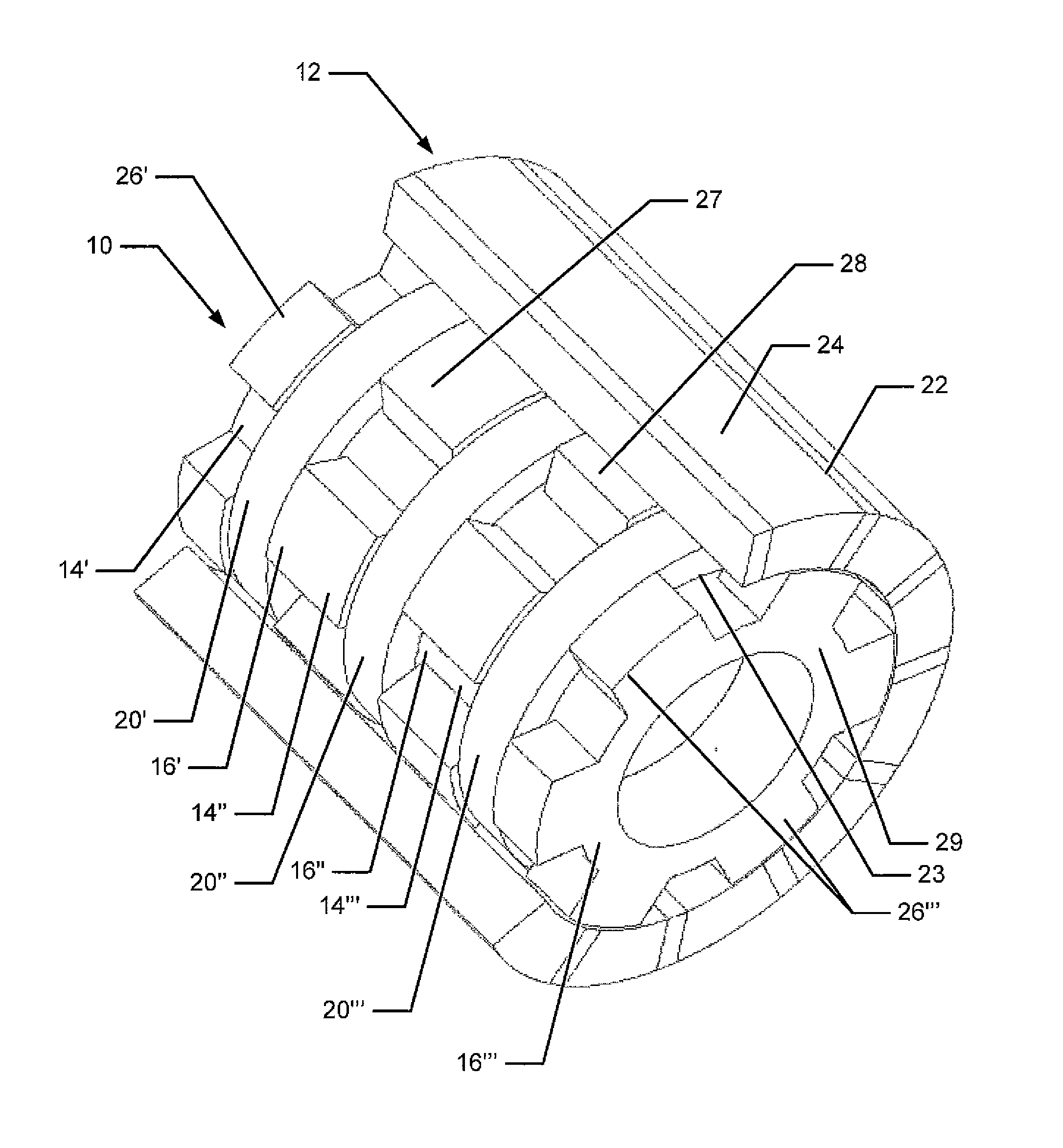
[0063]FIGS. 1-4 show examples of a three-phase machine with separate phases, which may be termed a Separate Phase Modulated Pole Machine (SPMPM).

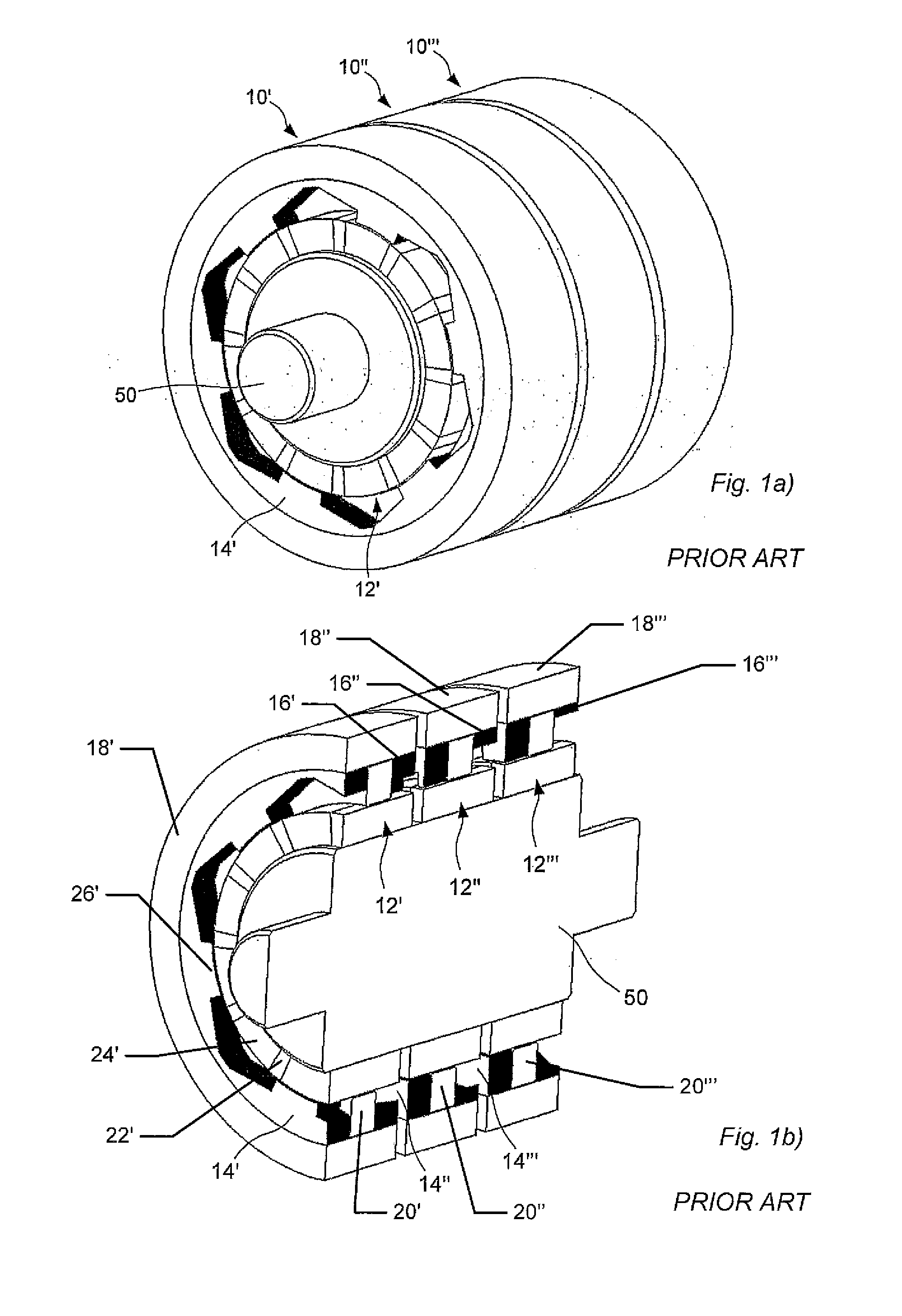
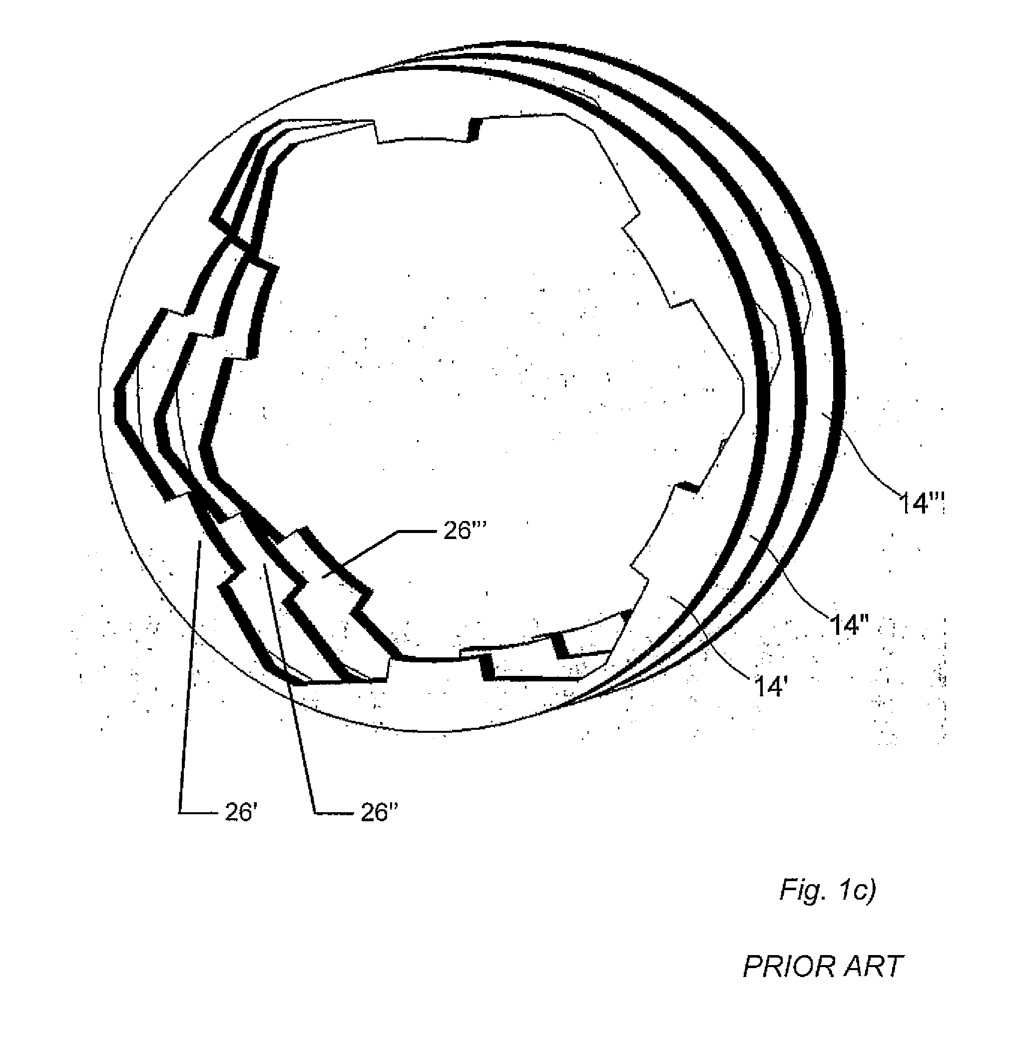
[0064]FIGS. 1a)-1b) show an example of a prior art three-phase radial machine. An electrical, rotary machine comprises a stator assembly and a rotor. For the purpose of the present description, primed reference numerals with ′ generally refer to a feature of a first phase, ″ to a corresponding feature of a second phase and ′″ to a corresponding feature of a third phase, while reference numerals without prime refer to the corresponding features of all phases. Three stator assemblies 10′, 10″, 10′″ are shown, and each stator assembly comprises a first stator core section 14, a second stator core section 16, a stator yoke section 18 and a coil 20. Three rotors 12′, 12″, 12′″ are shown, and each...


PUM


Abstract

Disclosed is a stator device adapted to be arranged in an electrical machine, where the electrical machine further comprises a moving device,where the stator device is a multi-phase stator device, where the phases are arranged side-by-side in a direction perpendicular to direction of motion of the moving device, and where each phase comprises a first stator core section having a set of teeth, a second stator core section having a set of teeth, and a coil, and where the teeth are arranged to protrude towards the moving device; andwherein at least two neighbouring phases share a stator core section, so that the first stator core section of a first phase and a second stator core section of a second phase is formed as a single unit.

Description

FIELD OF THE INVENTION[0001]This invention generally relates to electric machines. More particularly, the invention relates to a rotating or linearly moving three-phase transverse flux machine with a permanent magnet rotor or mover structure. This type of machine could be utilized either as a motor or a generator depending on the area of application. A linearly moving machine may also be denoted a linear machine, a transversally moving machine or a translational moving machine.BACKGROUND OF THE INVENTION[0002]The transverse flux machine (TFM) topology is an example of a modulated pole machine. It is known to have a number of advantages over conventional machines. The basic design of a single-sided radial flux stator is characterized by a single, simple phase winding parallel to the air gap and with a more or less U-shaped yoke section surrounding the winding and exposing in principal two parallel rows of teeth's facing the air gap. The state-of-art multi-phase arrangement is charact...

Claims


Application Information

Patent Timeline
09 Aug 2012
Publication
US20120200177A1
IPC
H02K1/12; H02K41/03; H02K1/02
CPC
H02K1/145; H02K21/145; H02K41/02; H02K2201/12; H02K3/12; H02K41/03; H02K1/17
Inventors
ATKINSON, GLYNN JAMES; JACK, ALAN G.