Infrared-light and low-light two-phase fusion night-vision sighting device

a two-phase fusion and infrared light technology, applied in the field of infrared light and low-light two-phase fusion night-vision sighting devices, can solve the problems of increased shooting difficulty and unstable shooting accuracy, and achieve the effects of stable display, quick and accurate sighting, and simple shooting calibration

Active Publication Date: 2018-02-20
HUNTERCRAFT
View PDF3 Cites 4 Cited by
  • Summary
  • Abstract
  • Description
  • Claims
  • Application Information

AI Technical Summary

Benefits of technology

[0004]In order to solve the above problems, the present invention provides a night-vision sighting device featured by quick fusion of night-vision image processing, stable displaying, clear night-vision image boundary, simple shooting calibration, quick and accurate sighting, enabled man-machine interaction, and enabled dual-eye sighting.
[0005]The invention provides an infrared-light and low-light two-phase fusion night-vision sighting device, the night-vision sighting device comprising a housing that defines an accommodation space, the accommodation space includes a field-of-view obtaining unit, a two-phase fusion unit, a control unit, and a display unit, the two-phase fusion unit in the night-vision sighting device can convert the optical image obtained by the field-of-view obtaining unit into infrared digital image and low-light digital image, and transmit to the control unit, the infrared digital image and the low-light digital image is fusion-processed via the control unit, and displayed on the display unit, which facilitates user for sighting under low-brightness environment.
[0017]Further, the present invention also provides a calibration method for realizing precise shooting during shooting process of the night-vision sighting device, the calibration method is applied to the night-vision sighting device in the above embodiment, the calibration method comprising: setting a target within a field of view of the night-vision sighting device, measuring a distance from the night-vision sighting device to the target by a range-finding unit of the night-vision sighting device; invoking a plane coordinate via a key unit so as to load onto the display unit, and applying a coordinate center to sight; viewing the field of view of the display unit, controlling a gun, aligning the coordinate center with the target; upon alignment, shooting a first bullet, and obtaining a first impact point on the target, the display unit print-screening an image having the first impact point; and adjusting the field of view of a display screen of the night-vision sighting device, such that a center of the plane coordinate coincides with the first impact point; accomplishing the calibration.
[0019]Further, the calibration method may further comprise adding a second shooting calibration after the first shooting calibration, so as to enhance the preciseness of calibration.

Problems solved by technology

However, when the above night-vision device is applied, the brightness of the image displayed on a display screen progressively increases from the background to the sighted object, resulting in that distinction between the targeted object image boundary brightness and background brightness is not obvious, and the boundary of the targeted object is blurred, thus, the obtained night-vision image has blurred boundary, which makes the shooter only obtain the location and orientation of the targeted object, and it is difficult to determine an optimum sighting point, therefore, it requires the user to judge the sighting point by virtue of shooting experience, which increases shooting difficult, and also causes instability of shooting accuracy.

Method used


Image

  • Infrared-light and low-light two-phase fusion night-vision sighting device
  • Infrared-light and low-light two-phase fusion night-vision sighting device
  • Infrared-light and low-light two-phase fusion night-vision sighting device

Examples


Embodiment Construction

[0038]In order to make the objective, technical solution, and advantages of the present invention more elucidated, the present invention will be described in more detail with reference to the accompanying drawings and embodiments. It should be understood that the preferred embodiments described here are only for explaining the present invention, not for limiting the present invention.

[0039]On the contrary, the present invention covers any replacements, modifications, equivalent methods and solutions defined by the claims within the spirit and scope of the present invention. Further, in order to make the public understand better the present invention, some specific detailed portions are elaborated in the following depiction of the details of the present invention.

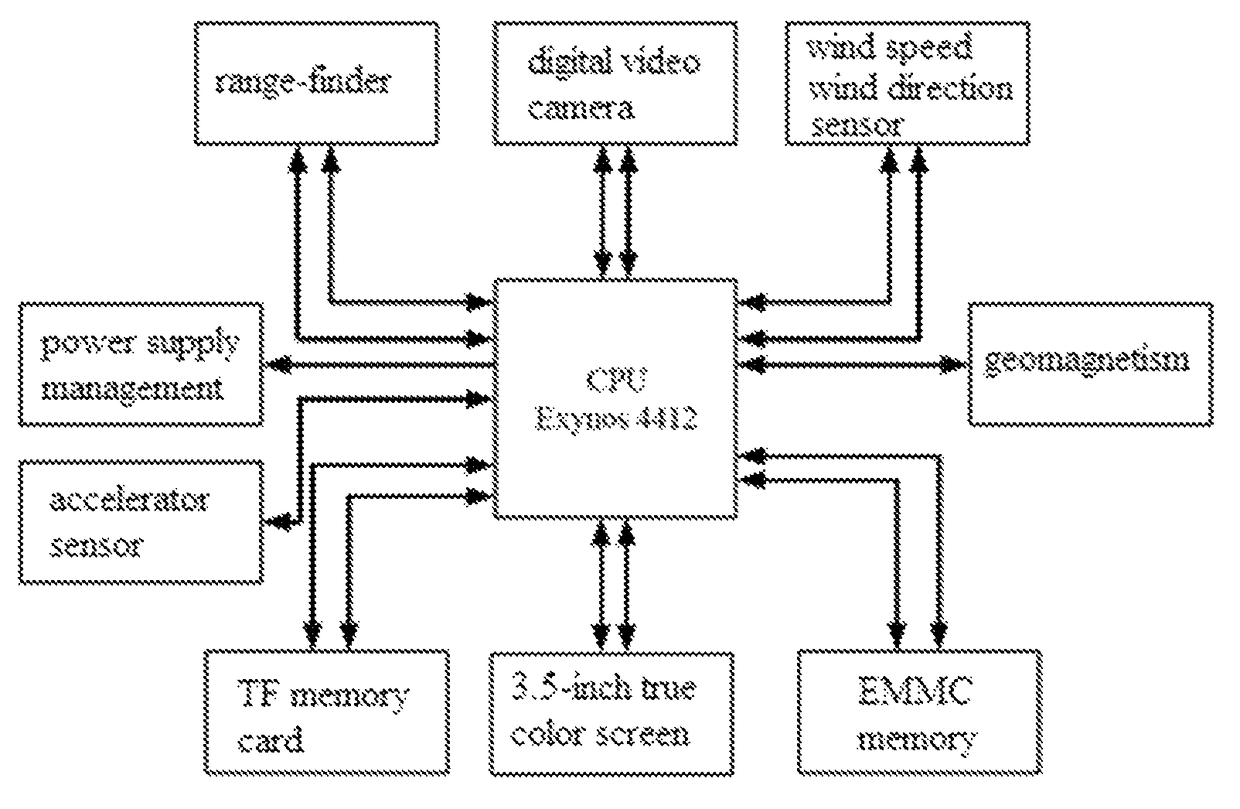
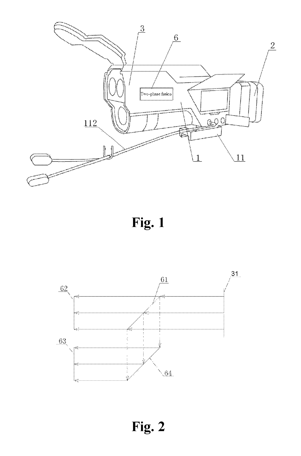
[0040]FIG. 1 shows a structural diagram of an embodiment of the present invention, an infrared-light and low-light two-phase fusion night-vision sighting device is provided in the embodiment of the present invention, the nig...


PUM


Abstract

The present invention relates to the technical field of sighting device, and specifically relates to an infrared-light and low-light two-phase fusion night-vision sighting device. The night-vision sighting device comprises a field-of-view obtaining unit, a two-phase fusion unit, a control unit and a display unit, the two-phase fusion unit in the night-vision sighting device can perform infrared-light and low-light fusion processing to the optical image obtained by the field-of-view obtaining unit, and display on the display unit, which realizes to obtain a night-vision image featured by image stabilization, clear outline, high resolution, high contrast, high SNR, and low pepper and salt noise, to thereby ensure night-vision sighting of the electronic gun sight under the condition of night or low brightness.

Description

TECHNICAL FIELD[0001]The present invention relates to the technical field of gun sight, and more specifically relates to an infrared-light and low-light two-phase fusion night-vision sighting device.BACKGROUND[0002]Traditional sights usually include mechanical sights and optical sights, wherein the mechanical sights generally refer to performing sighting mechanically through a metallic sight such as a rear sight, a front sight, and a notch; The optical sighting device utilizes optical lens to image, to make a target image and a line of sight superimposed on the same focal plane, thus, sighting is realized.[0003]In the prior art, in order to improve shooting accuracy, and adapt more shooting environments, more techniques are integrated on the electronic sighting device. For example, when a user performs hunting or shooting at night, a night-vision function can be applied on sighting device, then the sighting device can help users more accurately search for a targeted object, which fa...

Claims


Application Information

Patent Timeline
Patent Type & Authority Patents(United States)
IPC IPC(8): F41G1/32G02B27/32G02B27/10F41G1/38G06T3/00G06T5/00F41G3/06F41G3/08
CPCF41G1/32F41G1/38F41G3/06F41G3/08G02B27/1006G06T3/0068G06T5/002G02B27/32G06T2207/20221G06T2207/10048G06T2207/20182F41G3/065F41G3/165F41G1/36F41G1/383F41G1/473G06T5/50G06T2207/10024
Inventor ZHANG, LINSHI, CHUNHUASU, SANG
Owner HUNTERCRAFT
Why Eureka
Try Eureka