Supercharge Your Innovation With Domain-Expert AI Agents!

Position Sensing in a Probe to Modify Transfer Characteristics in a System

Active Publication Date: 2017-04-27
TEKTRONIX INC
View PDF9 Cites 3 Cited by
  • Summary
  • Abstract
  • Description
  • Claims
  • Application Information

AI Technical Summary

Benefits of technology

The patent describes a probe that can measure the position of an adjustable part of the probe and output a signal that indicates that position. The probe also includes a processor that can monitor the position signal and adjust the output of the probe to correct for changes in the electrical characteristics caused by the position change. The patent also describes methods for compensating for changes in the response of the test and measurement system caused by movement of the probe. The technical effects of this patent include improved accuracy and reliability of test and measurement systems, as well as simplified and efficient calibration methods.

Problems solved by technology

Physically probing a DUT test point can be challenging, especially when the electrical components are very small, or when there are a large number of components packed into a small area.
In these cases, the test points of interest can be difficult to access since they may be obscured by other components, cables, or mechanical features of the DUT.
When a part of the probe in the signal path changes positions, this generally tends to change an electrical characteristic of the probe, potentially to the extent that the probe no longer performs within its specifications.
This in turn can lead to an inaccurate measurement of the signal in the DUT.
However, conventional adjustable probes are not able to compensate for such electrical characteristic changes to return the performance of the probe to within specification.

Method used


Image

  • Position Sensing in a Probe to Modify Transfer Characteristics in a System
  • Position Sensing in a Probe to Modify Transfer Characteristics in a System
  • Position Sensing in a Probe to Modify Transfer Characteristics in a System

Examples


Embodiment Construction

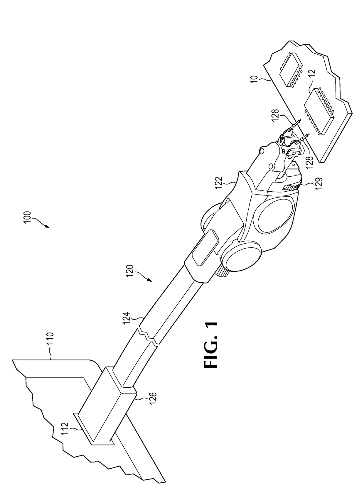
[0017]FIG. 1 depicts an example test and measurement system 100. The test and measurement system 100 includes a test and measurement instrument 110, such as an oscilloscope, as well as a test and measurement probe 120. The test and measurement probe 120 connects to an input 112 of the test and measurement instrument 110. The probe 120 may be used to make electrical contact with one or more test points in a user's device-under-test (DUT) 10, which may be a circuit board. For example, the probe 120 may be positioned by a user to make physical contact with one or more pins on an integrated circuit (IC) 12 placed on the circuit board 10, in order to monitor the electrical signal present at those points in the DUT 10, that is, the “measured signal.”

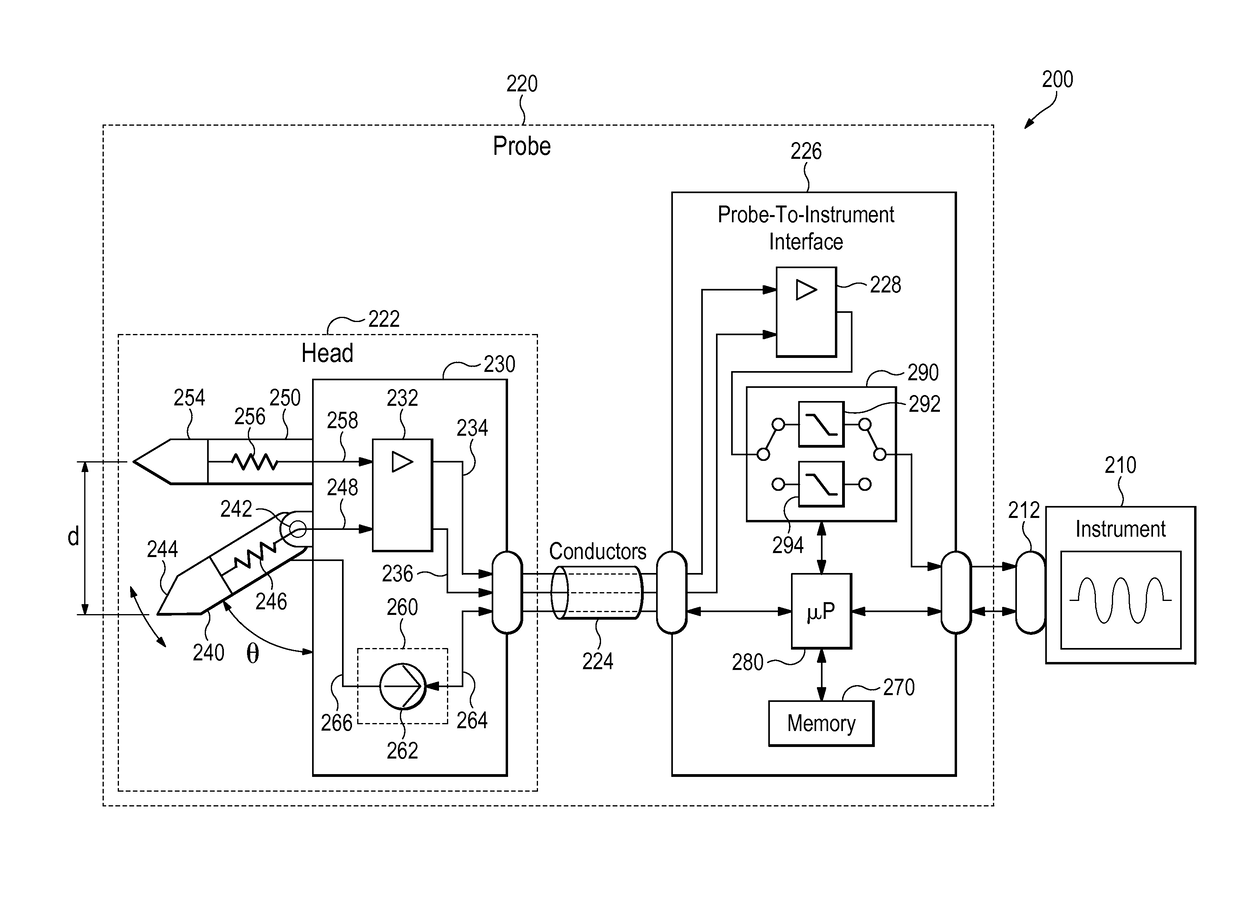
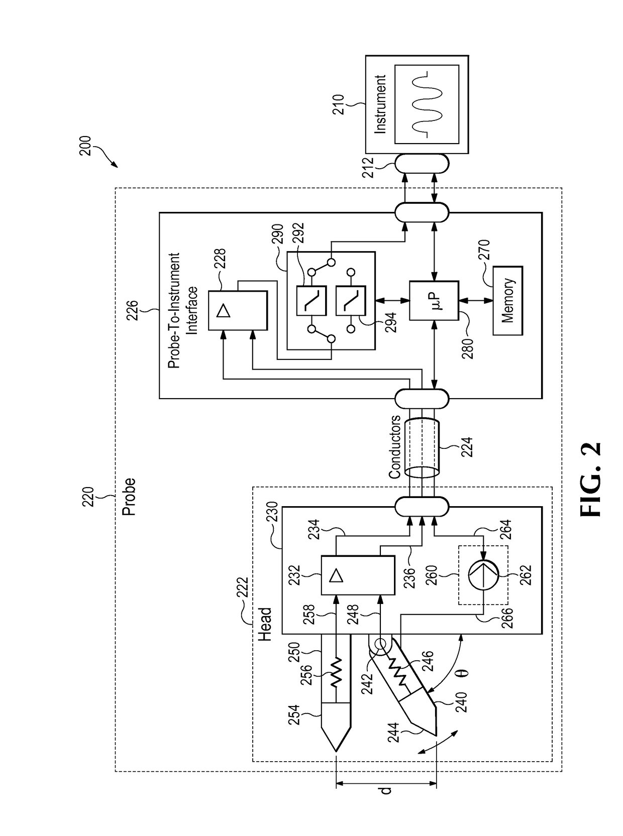
[0018]The probe 120 generally includes a probe head 122, a probe-to-instrument interface 126, and one or more conductors 124 between the probe head 122 and the probe-to-instrument interface 126. As a browser probe, the probe head 122 is genera...


PUM


Abstract

Test and measurement probes include a body, an adjustable member moveably coupled to the body and having a changeable position relative to the body, and a transducer subsystem structured to measure the position of the adjustable member and configured to output a position signal indicative of the position of the adjustable member. A change in the position of the adjustable member causes a change in an electrical characteristic of the probe. A position-dependent correction factor may be used to correct the change in the electrical characteristic. Methods of compensating for a change in a response of a test and measurement system include monitoring a position sensor output to detect a position change of a first part of a probe relative to a second part, determining that the position sensor output value has crossed a boundary value between a first and second range, and applying a compensation factor corresponding to the second range to modify the response of the system.

Description

TECHNICAL FIELD[0001]This disclosure relates to test and measurement systems, and more particularly to probes in test and measurement systems.BACKGROUND[0002]Users of a test and measurement instrument, such as an oscilloscope, often use a probe to connect a device-under-test (DUT), such as a circuit board, to an input of the test and measurement instrument in order to visualize, debug, and perform measurements of electrical signals occurring in the DUT. To measure an electrical signal in a DUT, a user typically needs to establish physical contact between the probe and one or more test points of interest in the DUT. Test points may be located in various places on a DUT circuit board and may be traces or vias, connector pins, or component pads or pins, such as the pins of an integrated circuit (IC). Physically probing a DUT test point can be challenging, especially when the electrical components are very small, or when there are a large number of components packed into a small area. I...

Claims


Application Information

Patent Timeline
IPC IPC(8): G01R1/067G01R1/073G01R35/00
CPCG01R1/06766G01R1/073G01R35/005G01R1/06794
Inventor CAMPBELL, JULIE A.BARTLETT, JOSIAH A.SAILOR, DAVID A.SCHWICHTENBERG, JAY
Owner TEKTRONIX INC
Features
  • R&D
  • Intellectual Property
  • Life Sciences
  • Materials
  • Tech Scout
  • Unparalleled Data Quality
  • Higher Quality Content
  • 60% Fewer Hallucinations
Learn More