Multifunctional aerodynamic, propulsion, and thermal control system

a control system and multi-functional technology, applied in the direction of machines, light and heating equipment, transportation and packaging, etc., can solve the problems of overheating the thermal environment and the electronics contained within the environment, energy is not easily dissipated from the thermal environment, and the electronics generated by operating electronics cannot be easily dissipated. , to achieve the effect of reducing the drag of the flight vehicl

Active Publication Date: 2017-05-11
RAYTHEON CO
View PDF4 Cites 4 Cited by
  • Summary
  • Abstract
  • Description
  • Claims
  • Application Information

AI Technical Summary

Benefits of technology

[0015]Performing at least one secondary use may include blowing the working fluid out of the flight vehicle to reduce a base drag of the flight vehicle.

Problems solved by technology

The energy generated from operating the electronics may overheat the thermal environment and the electronics contained within the environment.
Furthermore, in some applications, the energy is not easily dissipated from the thermal environment.

Method used


Image

  • Multifunctional aerodynamic, propulsion, and thermal control system
  • Multifunctional aerodynamic, propulsion, and thermal control system
  • Multifunctional aerodynamic, propulsion, and thermal control system

Examples


Embodiment Construction

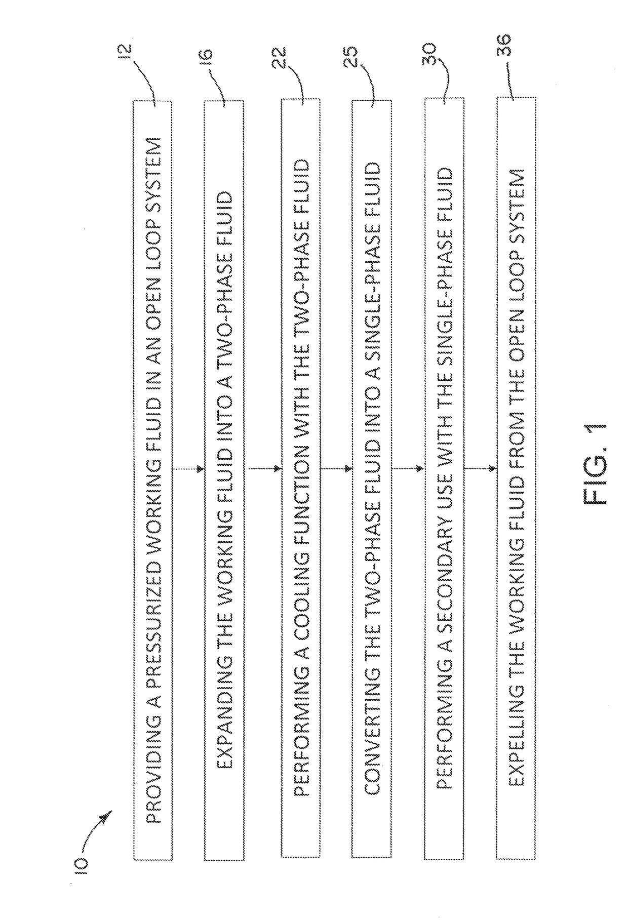
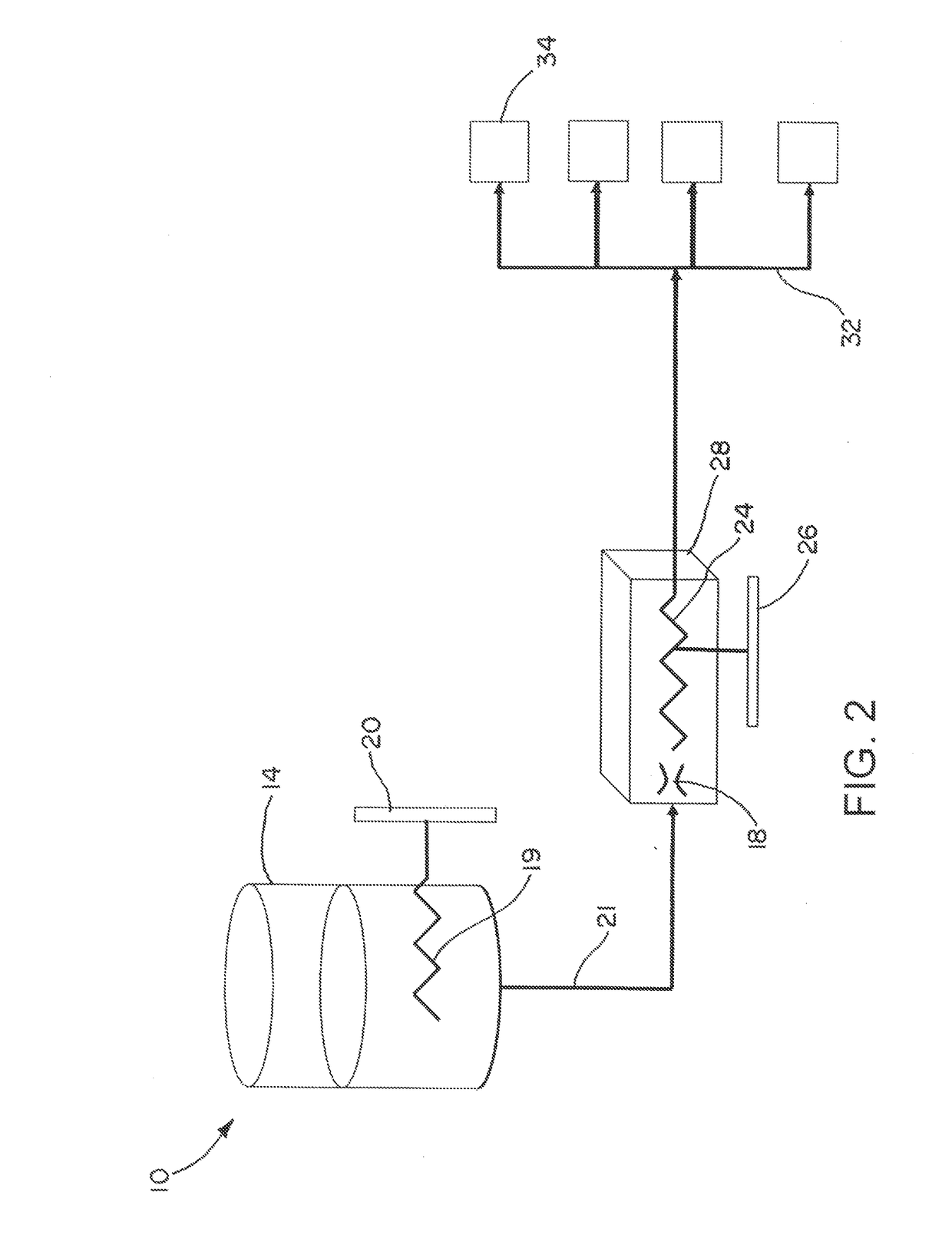
[0022]An open-loop thermal control system has a reservoir for containing a pressurized working fluid, a first heat exchanger in thermal communication with the working fluid in the reservoir, a Joule-Thomson expansion valve in fluid communication with the reservoir, and a second heat exchanger in fluid communication with the valve. The valve is configured to expand the working fluid into a two-phase fluid having a primary use of cooling. The first heat exchanger is configured to transfer heat from a source to the fluid in the reservoir. The second heat exchanger is configured to receive the two-phase fluid and provide a single-phase working fluid for at least one secondary use before the working fluid is expelled from the thermal control system. The second heat exchanger is configured to exchange heat with components that generate heat and need thermal control.

[0023]FIG. 1 is a flowchart showing an exemplary method of thermal control for components generating heat using an open-loop ...


PUM


Abstract

An open-loop thermal control system and method for components that generate heat includes a reservoir for containing a pressurized working fluid, a first heat exchanger in thermal communication with the working fluid, a Joule-Thomson expansion valve in fluid communication with the reservoir, and a second heat exchanger in fluid communication with the valve. The first heat exchanger is configured to transfer heat from the components to the fluid in the reservoir. The valve is configured to expand the working fluid into a two-phase fluid having a primary use of cooling. The second heat exchanger is configured to receive heat from the components and receive the two-phase fluid. The second heat exchanger provides a single-phase working fluid for at least one secondary use before the working fluid is expelled from the thermal control system.

Description

FIELD OF THE INVENTION[0001]The invention relates to thermal control systems, and more particularly to thermal control systems in air vehicles.DESCRIPTION OF THE RELATED ART[0002]Various applications have thermal environments. In certain applications, such as in air flight vehicles, the thermal environment includes internal electronics used for operating the air flight vehicle. The energy generated from operating the electronics may overheat the thermal environment and the electronics contained within the environment. Furthermore, in some applications, the energy is not easily dissipated from the thermal environment. In certain applications, functions such as electrical power generation, airframe cooling, active aerodynamics, and propulsion are also required and compete for the same space as the thermal control system.SUMMARY OF THE INVENTION[0003]According to an aspect of the invention, an open-loop thermal control system for components that generate heat includes: a reservoir for ...

Claims


Application Information

Patent Timeline
Patent Type & Authority Applications(United States)
IPC IPC(8): F42B15/34F25B9/02
CPCF25B9/02F42B15/34F25B19/005B64D27/00B64G1/40
Inventor LYONS, PAUL M.DANFORTH, JEREMY C.VOLLIN, JEFF L.SUMMERS, MATT H.
Owner RAYTHEON CO
Why Eureka
Try Eureka