Roadable aircraft with collapsible wings and ductless fan

a ductless fan and collapsible technology, applied in the direction of canard-type aircraft, aircraft convertible vehicles, efficient propulsion technologies, etc., can solve the problems of no commercial success, no commercial success, no design became commercially successful, etc., to eliminate complex and heavy ducting, maintain tension, and reduce the effect of cross wind resistan

Inactive Publication Date: 2013-08-20
BLOMELEY LEWIS E
View PDF31 Cites 18 Cited by
  • Summary
  • Abstract
  • Description
  • Claims
  • Application Information

AI Technical Summary

Benefits of technology

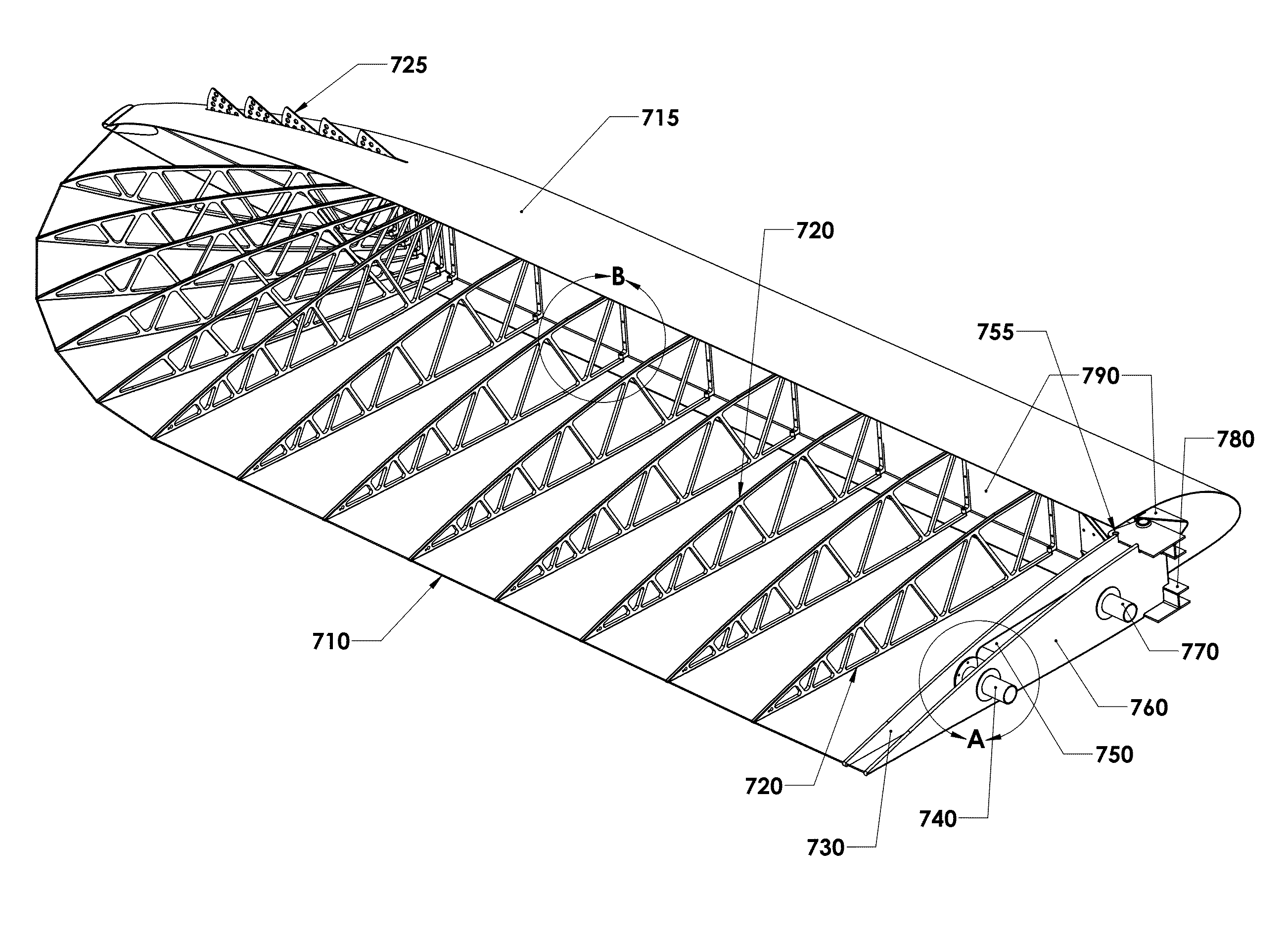
[0072]The foldable and collapsible wing of the present invention comprises a number of wing ribs, which are hinged to a main forward spar. To store for road usage, the wing ribs fold about a hinge to collapse against the wing spar. The wing skin is made of a flexible material, such as sailcloth (e.g., Nylon or Kevlar reinforced sailcloth or the like), which is more flexible than traditional doped wing fabrics and can collapse along with the wing ribs. The sailcloth may be configured as a tubular sleeve, which may wrap around the wing ribs and guides attached to the rib hinges. To maintain tension on the wing skin (to prevent flutter) a novel tensioning bladder or bladders may be used to maintain tension on the wing skin to keep the fabric taut. Once retracted and folded, the wings align with tail booms to form a compact and aerodynamic package, which provides low resistance to cross winds and the like.
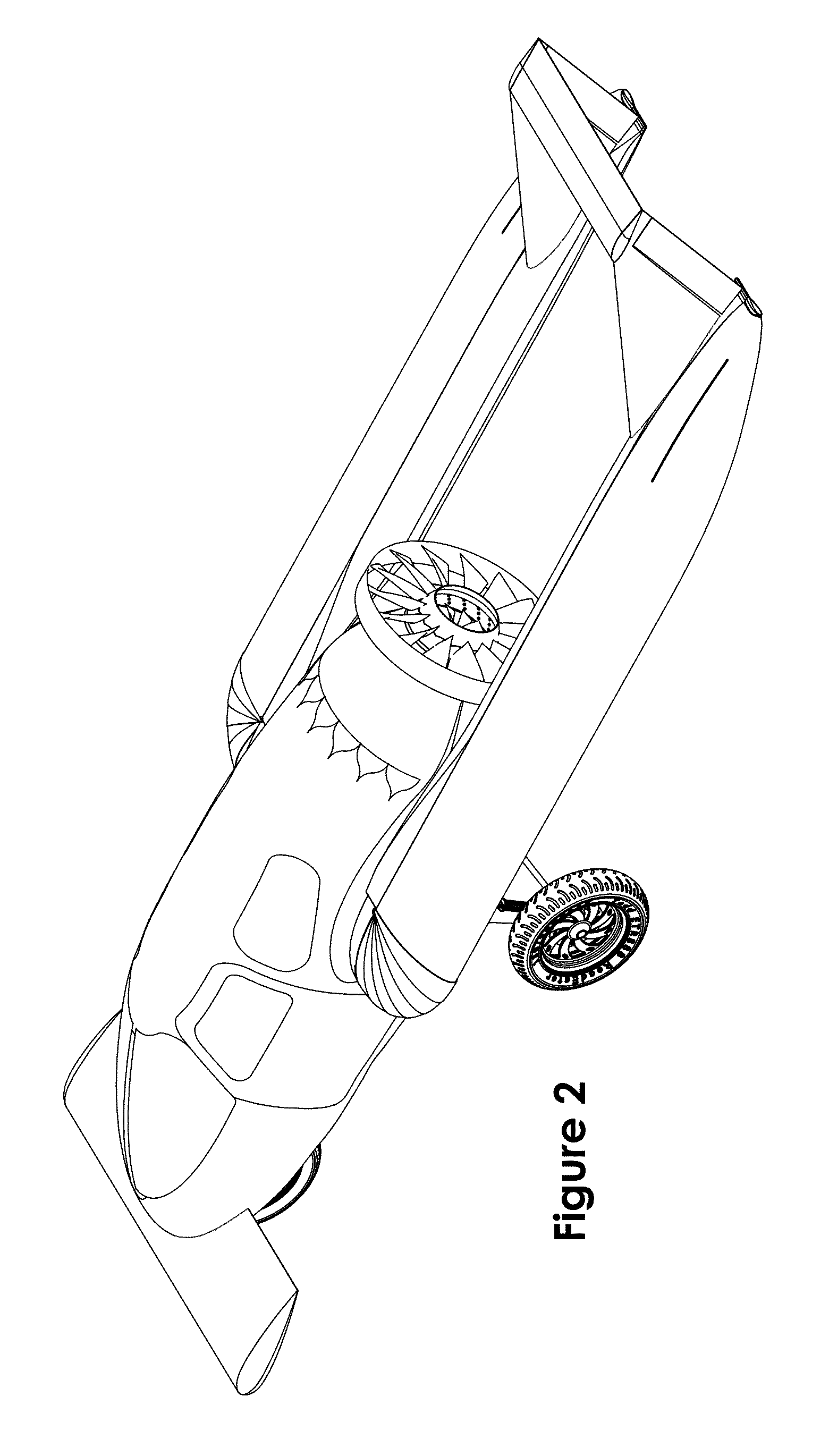
[0073]A ductless fan is used to propel the aircraft in the air. The “ductless” fan is similar to ducted fans in operation, but eliminates the complex and heavy ducting of the ducted fan. The shroud enclosing the ductless fan is integral to it, rather than separate as in a ducted fan. There is no relative motion between the fan blades and shroud, so the space between the blade tip and shroud is nil. This minimizes blade tip losses even better than a ducted fan, without the complexity and weight and drag penalties. In its simplest embodiment, the ductless fan would be fitted with a central aft facing fairing (spinner) that would help reduce base drag on the aft fuselage. The ductless fan is ideally suited to aircraft configurations requiring a minimum diameter means of propulsion.
[0074]This “ductless” fan may be coupled to a transmission and driven by the same engine as used for road power. In one embodiment, a Subaru® opposed-cylinder automotive engine is employed, suitably modified for aircraft use. Such engines are commonly used in Experimental Home Built category aircraft, and thus modification techniques for converting such engines for aircraft use are well known in the art. Such engines are readily available and have a history of reliable use in aircraft. An existing transmission and transfer case may be used to drive the road wheels, with the transfer case, ordinarily used to drive the other set of wheels of a 4 wheel drive vehicle, used to power the ductless fan when in the air. In this manner, the driveline can be constructed at minimal cost, using existing components, many of which have already been used in aircraft applications. When converting from flying to road use, the ducted fan may be disengaged for safety reasons. For flying use, the road wheels may be engaged to shorten takeoff runs and then may be left engaged or disengaged when airborne.
[0075]The ductless fan of the present invention may be provided with a center-mounted extraction fan in place of the central spinner. This center-mounted extraction fan may be ducted to inlets along the fuselage to draw air into the fuselage and thus prevent boundary layer separation. When using a short fuselage, such as for a pusher configuration aircraft, boundary layer separation may be a concern, as the short pusher fuselage results in abrupt taper and may promote separation of the boundary layer. This separation causes turbulence and resultant excess drag and which may lead to inefficient use of a pusher propeller or fan. By providing the central extraction fan, which may be driven from the main ducted rotor or through a separate transmission, air may be drawn into the fuselage through ports, ducts or slots, and then pushed out though the central extraction fan. This arrangement would not only prevent boundary layer separation but would eliminate the base drag of the propeller hub, and possibly even add thrust.

Problems solved by technology

However, in the long history of roadable aircraft, there has yet to be one design, which has met with any significant commercial success or adaptation.
While an example of the Waterman Aerobile is now in the Smithsonian Air & Space museum, the design never became commercially successful.
The project was abandoned two years later when a test flight crashed, killing the pilot.
While several designs (such as the Convair flying car and Molt Taylor's Aircar) have flown, none have enjoyed commercial success and those that have flown are not widely known to the general public.
While a number of the Aerocars were built, it was not a successful design in that it did not generate a profit or become widely adopted.
While Molt Taylor did successfully build a roadable aircraft, the design has a number of technical limitations.
The “car” portion of the design would never meet safety standards for automobiles today, and could not easily be made to meet such standards.
This arrangement was then towed behind the car as a single-wheel trailer configuration, which would make negotiating corners difficult, if not hazardous.
The large wing surfaces, when placed in trailer configuration, would be hard to handle in crosswinds, particularly with such a lightweight “car” towing them.
The long drive shaft used to connect to the tail mounted propeller also presented design and operation difficulties.
This would considerably shorten the takeoff roll.
Even with a detachable wing and engine structure, the overall aircraft weight is so high as to make the design impractical.
Building attachable wings to an automobile frame is therefore not a practical solution for a roadable aircraft, due to weight considerations.
In addition, requiring the user to detach wings and engine and leave them at an airport would limit the aircraft / automobile concept in use, as the pilot / driver would have to return to the airport where he left his wing / engine pod in order to take off again.
When Ford approached the U.S. Federal Aviation Administration (FAA) about regulatory issues, the critical problem was that the (then) known forms of air traffic control were inadequate for the volume of traffic Ford proposed.
In addition, the cost of certifying such an aircraft would be prohibitive, so Ford dropped the project.
While regulations concerning automobiles are extremely stringent and result in large weight penalties, motorcycles, defined generally as any vehicle with three wheels or less, are subject to much less government regulation and are considerably lighter on construction.
With a highway speed of 65 mph and airspeed of 115 mph, however, the Transition is only practical for relatively short commutes, and the wind sensitive folded wings make it unsuitable for driving on expressway.
These limitations hinder its utility considerably, and may thus limit its commercial viability as well.
Moller International continues to develop the Skycar M400, which is powered by four pairs of tandem Wankel rotary engines, and is approaching the problems of satellite-navigation.
Moller has been developing VTOL craft since the late 1960s, but no Moller vehicle has ever achieved free flight out of ground effect.
Urban Aeronautics' X-Hawk is a VTOL aircraft, which operates much like a tandem rotor helicopter, however it doesn't have the exposed rotors, which make helicopters dangerous for personal use.
This is accomplished by containing the rotors in large ‘ducts’, which make up most of the body of the craft; the requisite decrease in rotor size also decreases fuel efficiency.
While the use of telescoping wings seems to solve many of the problems of the Prior Art, it is unclear whether such wings can be made strong and light enough to practical use.
It is unclear whether such a fan could generate sufficient propulsion to fly the aircraft, given the extensive ducting and shrouding of the fan.
In addition, with the use of such a relatively short fuselage, the issue of boundary layer separation when using a ducted fan is an issue.
Note also the lack of tail surfaces for this design, which raises some stability issues.
However in this Hatrick device, the goal is to disrupt the boundary layer.
This fantastic design is clearly not practical.
However, this sucking fan appears to be gear driven from the propeller shaft and is very small in size.
Moreover, Leray does not disclose using such a sucking fan to draw air from the fuselage of the aircraft to control boundary layer separation.
This is another fantastic design, which does not seem practical.

Method used


Image

  • Roadable aircraft with collapsible wings and ductless fan
  • Roadable aircraft with collapsible wings and ductless fan
  • Roadable aircraft with collapsible wings and ductless fan

Examples


Embodiment Construction

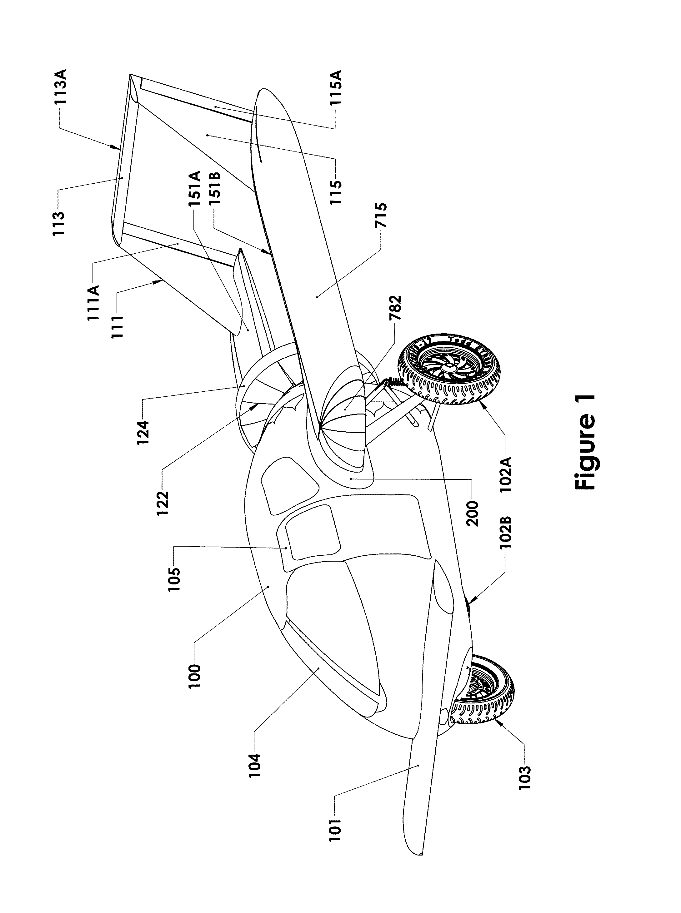
[0107]FIG. 1 is a front quarter perspective view of the roadable aircraft of the present invention, illustrated in a road-going configuration with wings collapsed and folded back for travel. FIG. 2 is a rear quarter perspective view of the roadable aircraft of the present invention, illustrated in a road-going configuration with wings collapsed and folded back for travel and showing more clearly the ductless fan of the present invention. FIG. 5 is a front quarter perspective view of the roadable aircraft of the present invention, illustrated in a road-going configuration with wings collapsed and folded back for travel.

[0108]Referring to FIGS. 1 and 2, an overall view of the roadable aircraft in road-going configuration is presented. The roadable aircraft of the present invention comprises a fuselage 100, which may be made of composites, riveted aluminum, traditional tube and fabric techniques, or any combination thereof. In the preferred embodiment, fuselage shell may be made of com...


PUM


Abstract

A roadable aircraft may be registered and driven as a motorcycle on the roadways, does not require that any parts be “left behind” at the airport when configuring to roadable use and does not require removing portions of the aircraft and towing them behind. A foldable and collapsible wing comprises a number of wing ribs, which are hinged to a main forward spar. To fold for road usage, the wing ribs fold about a hinge fitting to collapse against the wing spar. To maintain tension on the wing skin (to prevent flutter) tensioning bladder(s) may be used to keep the fabric taut. Once retracted and folded, the wings align with tail booms to form a compact and aerodynamic package. The ductless fan may be provided with a center-mounted extraction fan ducted to inlets along the fuselage to draw low energy air in toward the fuselage and thus prevent boundary layer separation.

Description

CROSS-REFERENCE TO RELATED APPLICATIONS[0001]The present application claims priority from Provisional U.S. Patent Application No. 61 / 144,486 filed on Jan. 14, 2009, and incorporated herein by reference.FIELD OF THE INVENTION[0002]The present invention relates to a roadable aircraft. In particular, the present invention is directed toward an aircraft, which is roadable, with attached collapsible wings, which may be registered as a motorcycle, and which is propelled by a ductless fan in flight.BACKGROUND OF THE INVENTION[0003]Roadable aircraft are well known in the art. The flying car or roadable aircraft may be defined as a vehicle, which may legally travel on roads and can take off, fly, and land as an aircraft. In practice, the vehicle usually has to be converted from a standard fixed-wing aircraft to one with sufficient roadworthiness. However, in the long history of roadable aircraft, there has yet to be one design, which has met with any significant commercial success or adaptat...

Claims


Application Information

Patent Timeline
Patent Type & Authority Patents(United States)
IPC IPC(8): B64C3/56B64C39/04B60F5/02
CPCB64C3/56B64C9/323B64C11/00B64C37/02B64C39/04B64C39/12Y02T50/145Y02T50/32Y02T50/44Y02T50/10Y02T50/30Y02T50/40
Inventor BLOMELEY, LEWIS E.
Owner BLOMELEY LEWIS E
Why Eureka
Try Eureka