
Crossbow with bowstring redirection

a bowstring and crossbow technology, applied in the field of crossbows, can solve the problems of difficult to achieve goals, complicated crossbows, and high cost, and achieve the effect of increasing kinetic energy and velocity and increasing velocity

Inactive Publication Date: 2013-11-12
ISLAS JOHN J
View PDF8 Cites 41 Cited by
  • Summary
  • Abstract
  • Description
  • Claims
  • Application Information

AI Technical Summary

Benefits of technology

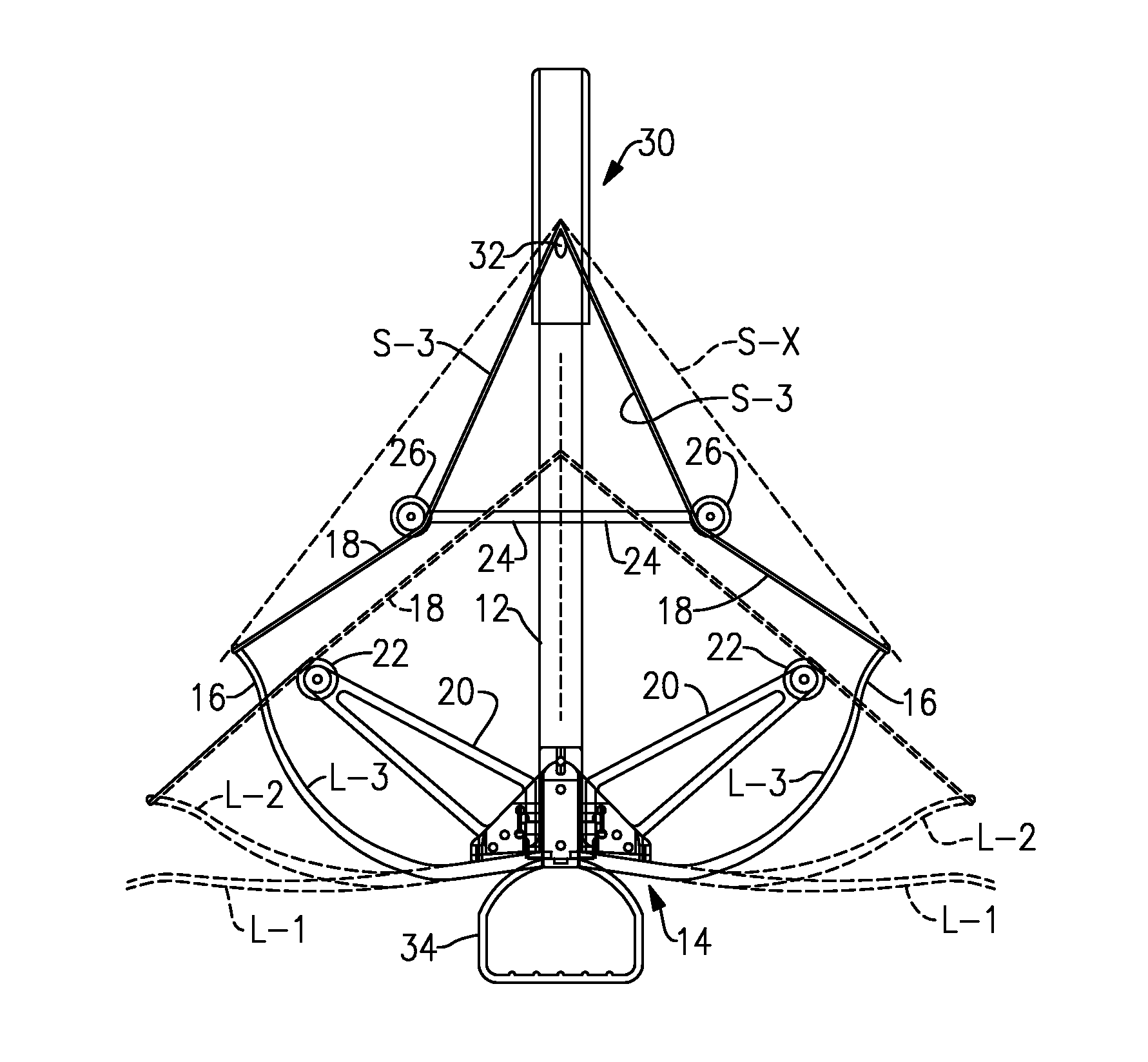
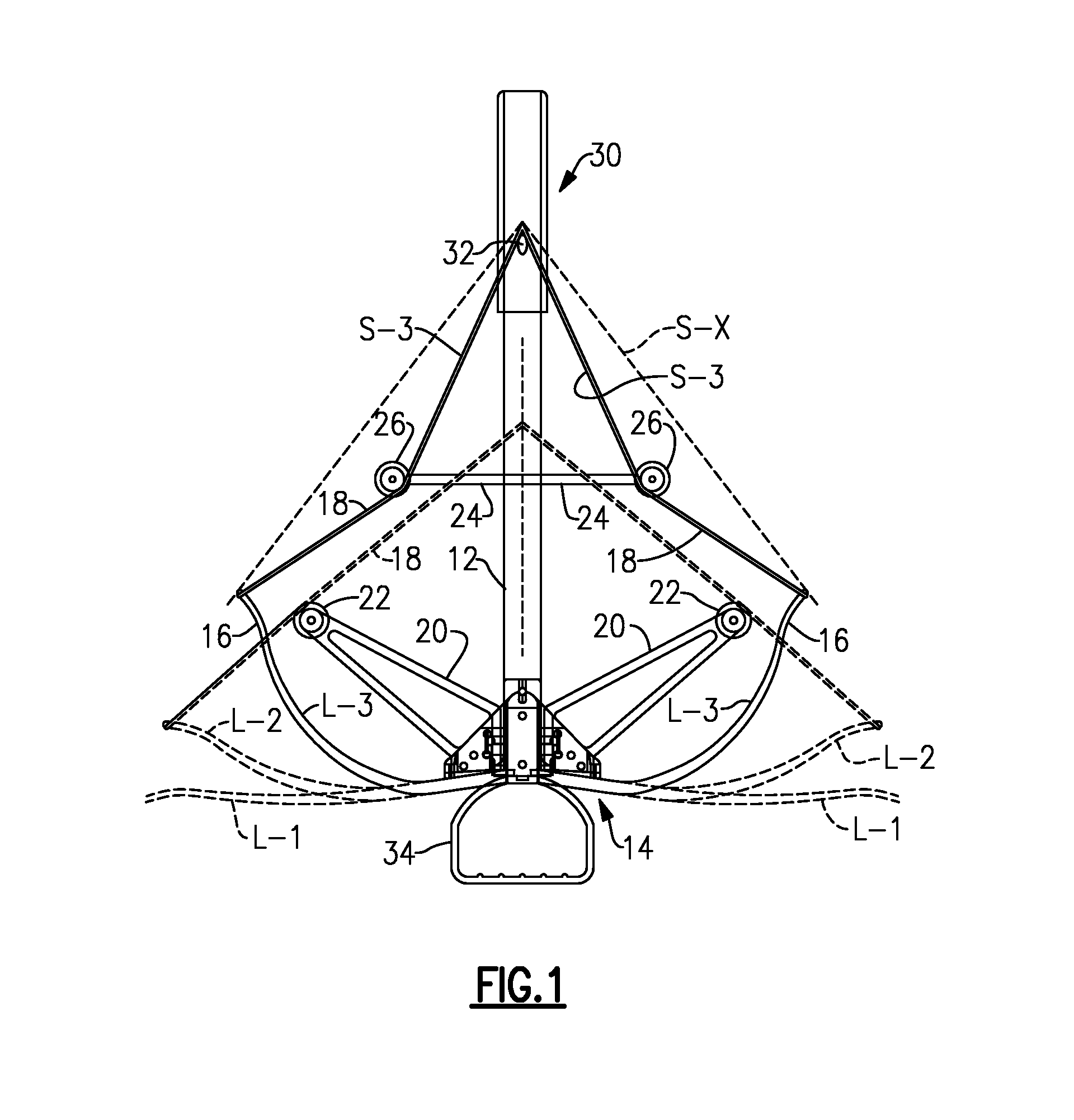
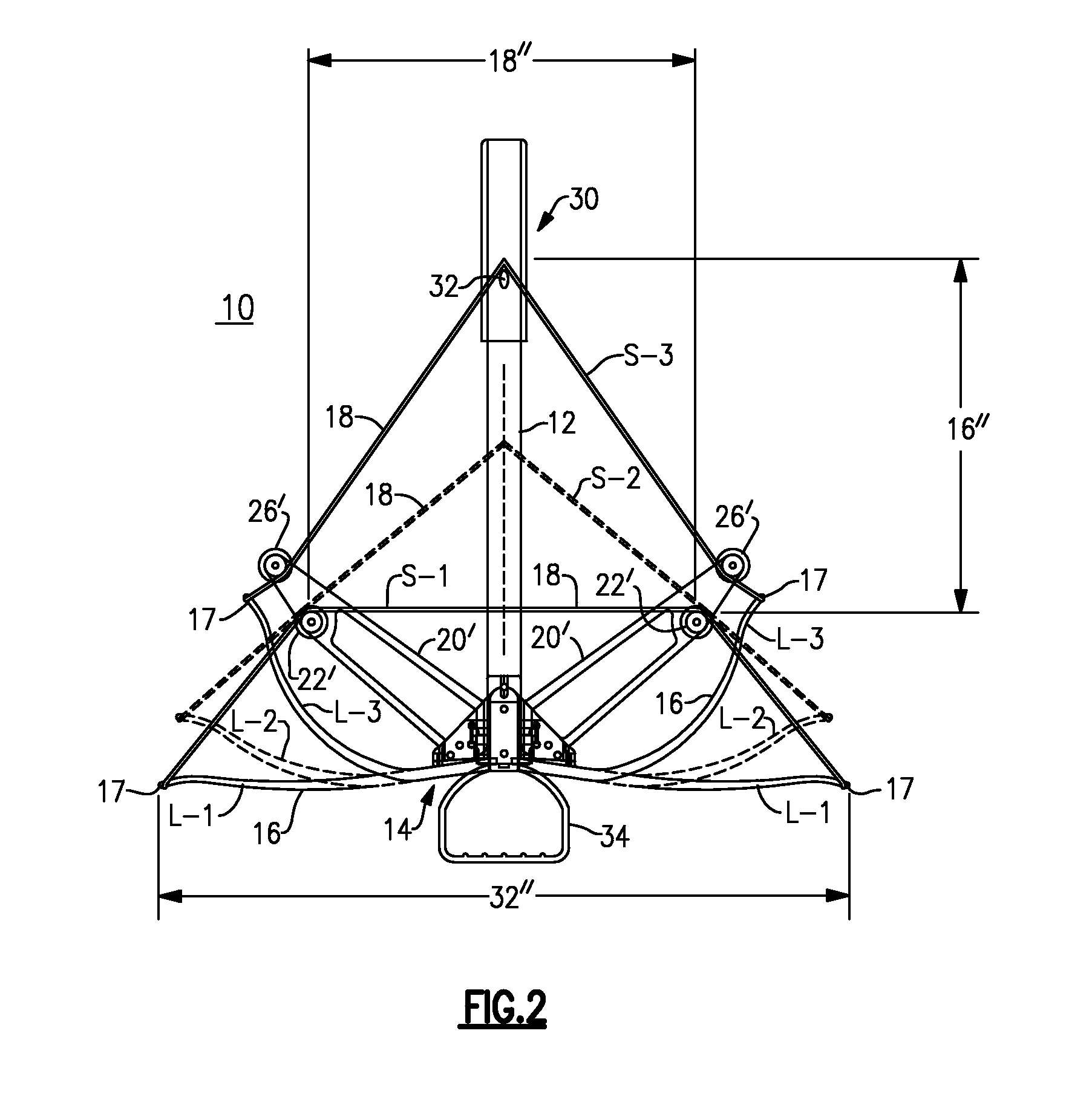
The invention is a crossbow with bowstring re-directing wheels or pulleys that are supported on support struts positioned proximally of the recurve limbs. This allows the bowstring to apply tension in a direction more or less tangent to the bend axis of the limb, rather than having a tension component angled out from the limb. The crossbow has a stock or beam with a proximal end and a distal end, with a bow mounted at the forward or distal end of the stock. The bowstring is secured at its ends at anchor points that are fixed relative to the stock, and passes over a pair of pulley wheels that are positioned at the ends of the spring limbs. The re-direction of the bowstring through its travel from full brace to release creates a mechanical advantage in the travel of the bow, resulting in significantly higher velocity. The crossbow has strut members or pylons with left and right re-directing wheels mounted thereon, positioned proximally of the bow and distally of the proximal end of the stock. The re-directing wheels are adapted to contact the bowstring at different positions, achieving an increased transfer of kinetic energy to the projectile. The reduced movement of the spring limb assists in keeping the bowstring aligned with the force vector of the spring limb, and makes the crossbow smaller laterally, which is an advantage to the archer.

Problems solved by technology

Crossbows that include means to regulate their draw weight typically take the form of compound bow systems, with various cams and cables, which make the crossbows complicated and expensive.
These goals have been difficult to achieve.
Some inefficiencies are due to mechanical losses in the crossover strings and pulley mechanisms that have universally been employed in compound bow systems.

Method used


Image

  • Crossbow with bowstring redirection
  • Crossbow with bowstring redirection
  • Crossbow with bowstring redirection

Examples


Embodiment Construction

[0014]The invention is explained in terms of a possible preferred embodiment, here a crossbow 10, in which there is an axial beam or stock 12 defining a medial plane with a recurve bow 14 that extends transversely across the front or distal end of the stock or beam. At the right and left of the recurve bow 14 there is a spring limb 16, i.e., a spring limb at the right side and one at the left side. A bowstring 18 is anchored at each end at an eye or anchor point 17 at the end of the respective limb 16.

[0015]As shown in FIG. 1, there is a set of right and left distal struts or pylons 20 in which are mounted left and right redirecting wheels or pulleys 22. These wheels 22 contact the bowstring 18 when the limbs 16 are forward i.e. when the crossbow is fully released. In this embodiment, there is a second set of transverse struts or pylons 24 located farther back along the beam or stock 12 with a respective right and left rearward re-directing wheels or pulleys 26. These wheels 26 are ...


PUM


Abstract

A crossbow employs bowstring redirecting wheels, over which the bowstring travels, to keep the bowstring aligned with the main force vectors where the bowstring meets the tips of the crossbow power limbs or spring limbs. The bowstring is anchored to a fixed anchor points, which can be on the pylons on which the redirecting wheels are mounted, or may be at the tips of the spring limbs. In one embodiment the bowstring passes over a pulley wheel at the tip of the spring limb. This crossbow arrangement achieves superior acceleration, and can be constructed of smaller transverse dimension than conventional or compound crossbows.

Description

[0001]This application claims priority under 35 U.S.C. §119(e) of Provisional Pat. Appln. 61 / 619,980, filed Apr. 4, 2012, the disclosure of which is incorporated herein by reference.BACKGROUND OF THE INVENTION[0002]This invention is directed to the field of archery, and more specifically to crossbows with features to program the draw weight to optimize the energy and velocity of the projectiles launched from the crossbow. Applicant incorporates by reference Published Application US 2011-0308508, Dec. 22, 2011.[0003]Crossbows that include means to regulate their draw weight typically take the form of compound bow systems, with various cams and cables, which make the crossbows complicated and expensive.[0004]It is an objective of modern crossbows to transfer to the bolt or arrow as much as possible of the energy that is stored in the bow, so that the projectile will fly faster and farther. These goals have been difficult to achieve. Some inefficiencies are due to mechanical losses in ...

Claims


Application Information

Patent Timeline
Patent Type & Authority Patents(United States)
IPC IPC(8): F41B5/12
CPCF41B5/123
Inventor ISLAS, JOHN J.
Owner ISLAS JOHN J
Learn More